 LKprototype
CNC machining tolerances tell us how much a part’s size can change. These tolerances are important so parts fit and work right. If you do not use tolerances, parts might break or not fit together. ISO 2768 is a main standard for CNC machining. When you use ISO 2768, machines make parts with the right size and shape. This means there are fewer mistakes and better quality. It also helps make things faster and stops errors from setting tolerances for every part. Knowing about ISO tolerance classes and good ways to use them helps you make parts better and have fewer mistakes.
ISO 2768 makes products better by using set tolerances.
It helps make parts more exact and correct.
The standard saves money by making production faster.
It stops mistakes and fixes by not needing many different tolerance settings.
Key Takeaways
Learn about CNC machining tolerances so parts fit well and work right. ISO 2768 gives rules to follow.
Pick the best tolerance class for your part. Choose Fine, Medium, Coarse, or Very Coarse. This helps balance cost and quality.
Use general tolerances for most parts. This saves time and money. Use tight tolerances only for important features that need accuracy.
Show tolerances clearly on engineering drawings. This stops mistakes and makes sure parts are made right.
Talk with your CNC shop about which materials to use. Discuss tolerance limits to make production better and cut down errors.
CNC MACHINING TOLERANCES OVERVIEW
WHAT ARE CNC MACHINING TOLERANCES?
CNC machining tolerances show how much a part’s size can change and still work. These tolerances set the highest and lowest sizes a part can be. You see them on engineering drawings for both straight and angled measurements. In CNC machining, you need to know the different types of tolerances. Here is a table with the most common types:
Tolerance Type | Description |
|---|---|
Standard Tolerances | Used a lot to show how much a CNC part’s size can change. |
Limit Tolerances | Shows the smallest and biggest size allowed on a drawing. |
Unilateral Tolerances | Tolerance goes in only one direction, either plus or minus. |
Bilateral Tolerances | Lets the size change both above and below the main size. |
Geometric Dimensioning and Tolerancing (GD&T) | Shows how much the shape of a part can change, not just its size. |
WHY TOLERANCES MATTER IN CNC MACHINING
Tolerances help make sure parts fit and work together. If you pick the right tolerances, you stop problems like loose parts or things that do not fit. For example, if a part should be 2.550″ with a ±0.001″ tolerance, it can be from 2.549″ to 2.551″. Smaller tolerances mean more exact parts, but they cost more. Bigger tolerances are easier and cheaper to make. Only use tight tolerances when you really need perfect fits.
Experts say to use strict tolerances only where needed. Using too many tight tolerances can waste money.
STANDARD VS PRECISION MACHINING TOLERANCES
There are two main groups: standard machining tolerances and precision tolerances. Standard machining tolerances usually start at ±0.1 mm (about 0.004″) for most metals. These work for many parts. If you need more accuracy, use precision tolerances. Precision tolerances can be as small as ±0.025 mm (about ±0.001″). For very exact parts, you might need tolerances as tight as ±0.001″ (±0.025 mm). You use these for parts that must fit just right. Most projects use general tolerances for straight and angled sizes unless you need high accuracy. Always pick the right tolerance to keep costs low and quality high.
UNDERSTANDING ISO 2768 TOLERANCE STANDARDS
WHAT IS ISO 2768?
You use iso 2768 tolerance standards to set clear rules for how much a part’s size or shape can change. This standard helps you avoid confusion on engineering drawings. Iso 2768 gives you a simple way to show tolerances for most CNC machined parts. You do not need to write a tolerance for every single measurement. Iso 2768 covers both general tolerances and geometric tolerances. You can see the main categories in the table below:
Category | Description |
|---|---|
General Tolerances | Used for sizes and angles without special notes. It makes drawings easier to read. |
Linear Dimensions | Covers things like length, width, height, and thickness. These use different tolerance classes. |
Angular Dimensions | Deals with angles. Tolerances depend on the angle size and class. |
Geometrical Tolerances | Checks shape and position so parts work together. |
Flatness | Makes sure surfaces are even within set limits. |
Straightness | Keeps lines from bending too much. |
Perpendicularity | Keeps features at right angles to each other. |
Symmetry | Makes sure features are balanced around the center. |
Tolerance Classes | There are four classes: Fine, Medium, Coarse, and Very Coarse. Each matches how exact you need the part. |
ISO 2768-1 VS ISO 2768-2
Iso 2768-1 and iso 2768-2 are two parts of the iso 2768 standard. You use iso 2768-1 for sizes and angles. This part works for most mechanical drawings. Iso 2768-2 is for geometric tolerances like flatness, straightness, and symmetry. You use iso 2768-2 when you need to control shapes or positions. The table below shows the difference:
Standard | Scope | Application |
|---|---|---|
ISO 2768-1 | Used for sizes and angles | Works for most mechanical drawings |
ISO 2768-2 | Used for geometric tolerances (flatness, etc.) | Needed for shape and position control |
WHY ISO 2768 IS WIDELY USED IN CNC MACHINING
Many CNC shops use iso 2768 because it makes drawings easy to understand. Iso 2768-1 and iso 2768-2 help stop mistakes and save time. You do not have to write every tolerance. This standard has four tolerance classes: Fine, Medium, Coarse, and Very Coarse. You pick the class that fits your part. Iso 2768 helps parts fit and work well. It also keeps costs low and quality high.
ISO 2768-MK EXPLAINED
Iso 2768-mk is a common way to show both medium and coarse tolerances on drawings. The “m” means medium, and the “k” is for a certain geometric tolerance class. You use iso 2768-mk when you want good accuracy and easy manufacturing. The chart below shows how tolerances change with feature length:

When the feature length gets bigger, the allowed tolerance also gets bigger. This helps you pick the right class for your part. Iso 2768-mk gives you a good mix of accuracy and saving money.
ISO 2768 TOLERANCE CLASSES AND CHARTS
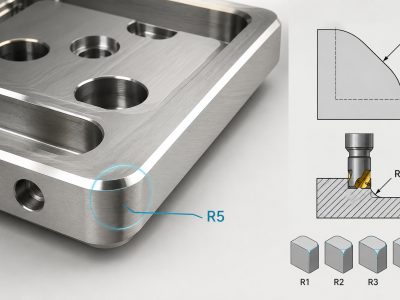
FINE (F) TOLERANCE CLASS
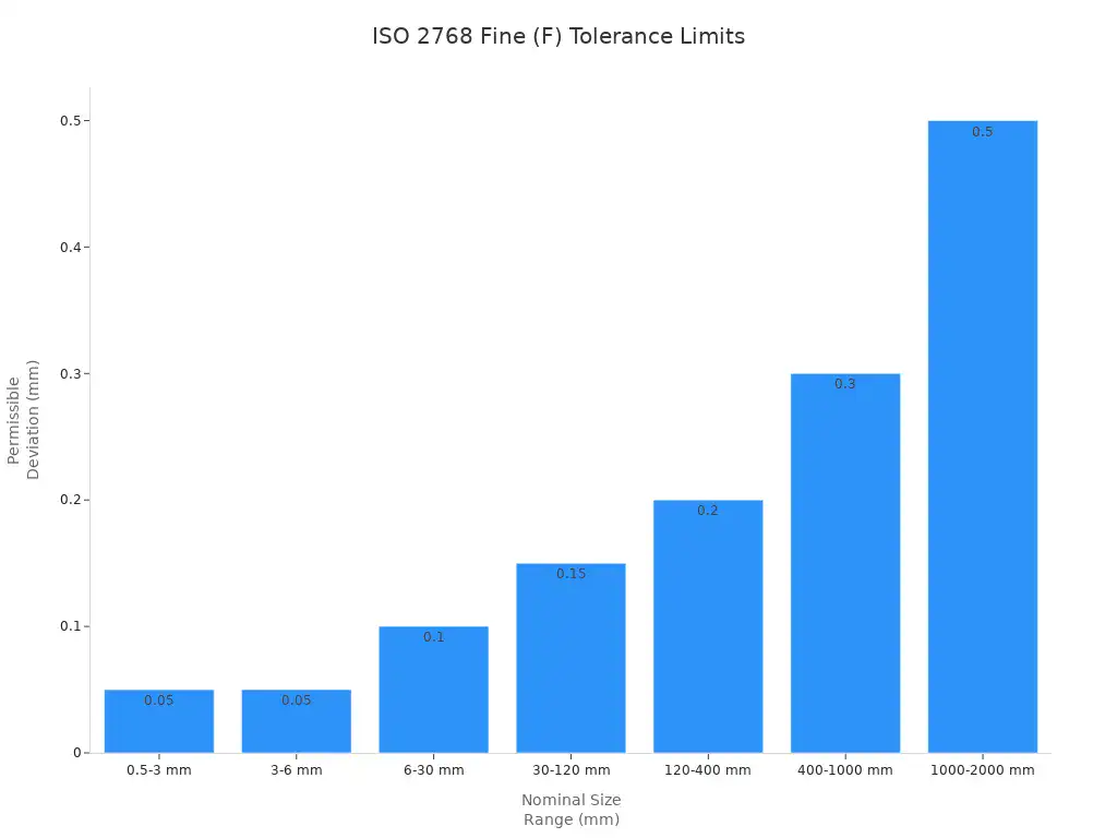
You pick the Fine tolerance class when you need very exact parts. This class is best for parts that must fit together just right or look perfect. Fine tolerances help control flatness, straightness, and how smooth a surface is. You often see Fine class in things like camera lenses or medical tools. The table below shows how much a part can change in size for the Fine class in iso 2768:
Nominal Size Range (mm) | Permissible Deviation (Fine - F) |
|---|---|
0.5 up to 3 | ±0.05 |
over 3 up to 6 | ±0.05 |
over 6 up to 30 | ±0.1 |
over 30 up to 120 | ±0.15 |
over 120 up to 400 | ±0.2 |
over 400 up to 1000 | ±0.3 |
over 1000 up to 2000 | ±0.5 |
over 2000 up to 4000 | - |
MEDIUM (M) TOLERANCE CLASS
The Medium tolerance class works for most projects. You use this class for things like phone cases, drone parts, and lab tools. Medium class gives a good mix of price and accuracy. It helps control flatness, straightness, and runout. Most engineers use Medium class for about 85% of jobs. You get ±0.1 mm control for many parts, which keeps making things simple and cheap.
COARSE (C) TOLERANCE CLASS
You choose the Coarse tolerance class when you want to save time and money. This class is good for big machines, mounting brackets, and strong parts. Coarse tolerances let flatness, straightness, and runout change more. These parts do not need to fit perfectly. Coarse class helps you finish work faster and spend less.
Industrial control panels
Equipment mounting brackets
Large structural components
VERY COARSE (V) TOLERANCE CLASS
Very Coarse tolerance class is for parts where exact size is not important. You use this class for big or simple parts that do not need tight fits. Very Coarse class lets flatness, straightness, and runout change the most. You see this class in building work or heavy machines.
HOW TO READ AN ISO 2768 TOLERANCE CHART
To read an iso 2768 tolerance chart, find your part’s size and match it to the right class. Each class—Fine, Medium, Coarse, or Very Coarse—shows how much your part can change. The chart also lists things like flatness, straightness, cylindricity, circularity, parallelism, perpendicularity, symmetry, coaxiality, and runout. You use these numbers to check if your part meets iso rules.
Tolerance Class | Description | Application Example |
|---|---|---|
M | Medium tolerances | General use in various components |
F | Fine tolerances | Precision parts requiring tighter limits |
C | Coarse tolerances | Larger parts with less precision needed |
V | Very coarse tolerances | Parts where high tolerances are not critical |
H | Geometric tolerance class | Used for specific geometric features |
K | Geometric tolerance class | Common in medium precision applications |
L | Geometric tolerance class | Used for less critical features |
ISO 2768 TOLERANCE TABLE REFERENCE
You can use the table below to compare the main iso 2768 tolerance classes for different part sizes. This table helps you pick the right class for your project and see how tolerances change as parts get bigger.
Nominal Length Range (mm) | Fine (F) Deviation (±mm) | Medium (M) Deviation (±mm) | Coarse (C) Deviation (±mm) |
|---|---|---|---|
0.5 up to 3 | 0.05 | 0.1 | 0.2 |
over 3 up to 6 | 0.05 | 0.1 | 0.3 |
over 6 up to 30 | 0.1 | 0.2 | 0.5 |
over 30 up to 120 | 0.15 | 0.3 | 0.8 |
over 120 up to 400 | 0.2 | 0.5 | 1.2 |
over 400 up to 1000 | 0.3 | 0.8 | 2.0 |
over 1000 up to 2000 | 0.5 | 1.2 | 3.0 |
over 2000 up to 4000 | N/A | 2.0 | 4.0 |

Tip: Always look at iso 2768 charts when you set general tolerances, surface roughness, and geometric features like flatness, straightness, runout, circularity, total runout, and symmetry. This helps you follow both iso and asme y14.5 rules.
CNC MACHINING PROCESS CAPABILITIES AND ACHIEVABLE TOLERANCES
CNC MILLING TOLERANCES
CNC milling can make parts with different accuracy levels. Most shops use standard tolerances for normal parts. If you need more exact parts, you can ask for tighter tolerances. This usually costs more and takes longer. The table below shows common ranges for metals:
Tolerance Band | Typical Numeric Range (Metals) | Expected Cost/Lead Time Pressure (Relative) |
|---|---|---|
Standard | ±0.1 mm to ±0.13 mm | Baseline |
Tight | ±0.025 mm | Higher (commonly cited 2–5× cost) |
Extreme | ±0.0127 mm (and below) | Project-specific (often dominated by metrology and stability) |
Standard tolerance for metals is about ±0.1 mm. For most jobs, general tolerances work unless your part needs a perfect fit.
CNC TURNING TOLERANCES
CNC turning gives results like milling. You can expect baseline tolerances of ±0.13 mm (±0.005″). For tighter parts, you can get ±0.025 mm. Turning depends on how worn the tool is and how you hold the part. The table below compares milling and turning:
Process | Baseline Tolerance | Tighter Tolerance | Dominant Error Source |
|---|---|---|---|
CNC Turning | ±0.13 mm (±0.005″) | ±0.025 mm | Sensitive to workholding and tool wear |
CNC Milling | ±0.13 mm (±0.005″) | ±0.025 mm | Affected by tool deflection and number of setups |
DRILLING AND BORING TOLERANCES
Drilling and boring set hole sizes in parts. Standard tolerance is ±0.1 mm, which works for most fits that are not critical. For tighter fits, you can get ±0.025 mm. Some special jobs need extreme tolerances down to ±0.0127 mm.
Tolerance Type | Metric Benchmark | Imperial Benchmark | Implications |
|---|---|---|---|
Standard Tolerance | ±0.1 mm | ~±0.004″ | Good for non-critical fits and general shapes |
Tight Tolerance | ±0.025 mm | N/A | Common goal for metals |
Extreme Tolerance | ±0.0127 mm | N/A | Micron-level results for parts needing high accuracy |
GRINDING TOLERANCES
Grinding helps you get the tightest tolerances in CNC machining. You use grinding for surfaces that must be very flat or round. You can reach tolerances as tight as ±0.005 mm in some cases. Grinding is best for finishing parts after milling or turning.
FACTORS THAT AFFECT MACHINING ACCURACY
Many things can change how close you get to your target size. You should pay attention to:
Material properties, like how much metal grows with heat.
Tooling conditions, such as sharpness and tool shape.
Machine maintenance, including calibration and lubrication.
Setup procedures, like how you hold the part and set tools.
Environmental stability, such as room temperature and humidity.
Tip: Always check your machine and tools before you start. Good habits help you keep cnc machining tolerances within your target range.
GD&T VS ISO 2768: WHICH TOLERANCE SYSTEM SHOULD YOU USE?
WHAT IS GD&T?
Geometric dimensioning and tolerancing, or GD&T, is a way to control the shape, size, and position of parts. You use symbols and datums to show how each part should look and fit. GD&T helps machinists and inspectors know what is most important. This system follows the ASME Y14.5 standard, which is used a lot in the United States. You see GD&T on drawings for parts that need to fit together very well, like in airplanes or medical tools.
KEY DIFFERENCES BETWEEN GD&T AND ISO 2768
You should know how iso 2768 and GD&T are different before you pick one. The table below shows the main differences:
Attribute | ISO 2768 | GD&T (ASME Y14.5) |
|---|---|---|
Origin | International (ISO), widely used in Europe, Asia, China | United States (ASME); dominant in US manufacturing |
Approach | General tolerance — one title-block callout covers most features | Feature-by-feature — each controlled feature needs an explicit GD&T symbol and datum reference |
Drawing complexity | Simpler, faster drawings; fewer annotations | More detailed drawings; higher engineering time upfront |
Geometric control | Limited to 5 geometric characteristics (ISO 2768-2) | Full GD&T suite: position, concentricity, profile, parallelism, cylindricity, and more |
Ambiguity | Some ambiguity for complex assemblies with critical fits | Highly precise and unambiguous when applied correctly |
Cost to apply | Low — fast drawing creation | Higher — requires trained GD&T engineers to apply and interpret correctly |
Best for | General machined parts, international sourcing, prototypes, most CNC components | Complex assemblies, aerospace/defense, parts requiring precise fit and function verification |
You use iso 2768 for most CNC parts, especially if you work with shops in China or Europe. GD&T is better for parts that need very exact shapes and fits.
WHEN TO USE GENERAL TOLERANCES
You should use general tolerances when you do not need very tight fits. These tolerances work well for sizes and shapes that are not critical. General tolerances keep drawings simple and help you make parts faster. They are good for making lots of parts and for parts where the shape does not matter much.
Use general tolerances for prototypes and regular CNC parts.
Pick iso 2768 when you want to save time and money.
Choose general tolerances for buying parts from other countries.
WHEN TO SPECIFY GD&T REQUIREMENTS
You need to use GD&T when your part has features that must fit together in a special way. GD&T helps you control things like position, parallelism, and symmetry. You should add GD&T symbols for features that need very tight control. Many engineers use both: they use iso 2768 for most features and add GD&T only where it is needed.
Tip: If you design parts for US airplanes or defense, you should use GD&T for all important features. For most other jobs, iso 2768 gives you enough control and makes things easier.
HOW TOLERANCES IMPACT MANUFACTURING COST AND QUALITY
COST IMPLICATIONS OF TIGHT TOLERANCES
If you ask for tight tolerances, your CNC parts cost more. Only use tight tolerances for features that really matter. For other parts, use general tolerances to keep costs low. Here are some important facts:
Changing from rough to precision tolerances can make parts four times more expensive.
Ultra-precision tolerances can cost up to 24 times more than standard machining.
Tight tolerances need special rooms and extra checks, which raise the price.
In fields like aerospace or defense, tight tolerances are needed for safety but make things much more expensive.
Tip: Use standard tolerance blocks for features that are not important. This helps avoid mistakes and makes manufacturing easier.
EFFECTS ON MACHINABILITY AND LEAD TIME
Tighter tolerances make parts harder to machine. You need more finishing steps and extra checks. This takes more time to make parts. Standard tolerances let you finish parts faster. High precision needs more setup and careful checking. This can double the cost and triple the wait time. Advanced CNC shops can still do strict jobs, but you will wait longer for your parts.
TOLERANCE STACK-UP CONSIDERATIONS
When you put many parts together, each part’s tolerance adds up. This is called tolerance stack-up. If you do not control stack-up, your product may not fit or work right. Good tolerance control keeps costs low, improves quality, and helps you get products out faster. Always check how tolerances add up in your assembly to stop problems later.
BALANCING QUALITY AND COST
You can balance quality and cost by using these ideas:
Set tight tolerances only where needed for fit, form, or function.
Use general tolerances for sizes that are not important.
Match tolerances to what your machines can do.
Do not use extra reference sizes to keep inspection costs low.
Check tolerance stack-up to make sure parts fit together.
Make fits better and think about material changes from heat.
If you follow these steps, you waste less, save money, and keep your parts working well. Clear and simple tolerance rules also help you work better with your suppliers.
BEST PRACTICES FOR SPECIFYING CNC MACHINING TOLERANCES
DESIGNING WITH MANUFACTURABILITY IN MIND
You should always think about how easy it is to make your part. Good design choices help you save time and money. Here are some tips you can use:
Design Tip | Description |
|---|---|
Eliminate draft angles | Makes machining simpler and improves part quality. |
Keeps parts strong and easy to machine. | |
Feature geometric simplifications | Reduces complexity and matches standard machining abilities. |
Avoid thin walls | Prevents weak spots and machining problems. |
Design fractional diameter holes | Helps parts fit and align better. |
Use bosses | Improves flatness and keeps parts stable during machining. |
You can also try to use fewer setups. Pick the best tool paths for your part. Turn your part the right way for easier cutting. These steps make machining go smoother and help you get better parts.
COMMUNICATING TOLERANCES ON ENGINEERING DRAWINGS
It is important to show your tolerances clearly on drawings. Use general tolerances for most features to keep things simple. For special features like bearing bores or sealing surfaces, you must show exact tolerances. Limit tolerances are good because they show the size range you can use. Always talk with your machine shop so you do not make mistakes. This helps your part come out right.
CHOOSING THE RIGHT TOLERANCE LEVEL
You need to pick the right tolerance for each part. Use tight tolerances only when parts must fit, seal, or move together. Think about the material you use. Softer metals and plastics can change shape when you cut them. Harder metals can wear out tools faster. Long tools, thin walls, and deep pockets can cause errors. Changes in temperature can also change your part’s size. If you add finishes like anodizing or plating, these can change the final size too. Tight tolerances cost more and take longer, so only use them when you really need them.
AVOIDING COMMON TOLERANCE MISTAKES
Many people make mistakes with tolerances. If you set tolerances too tight, your part will cost more and take longer to make. If you make them too loose, your part might not work right. You should know when to use general tolerances and when you need more precision. Always check your drawings for mistakes before you send them to the shop. This helps you avoid problems and keeps your project moving forward.
INSPECTION AND VERIFICATION OF CNC MACHINING TOLERANCES
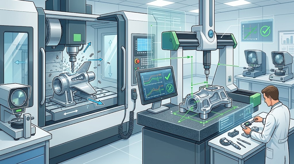
COMMON MEASUREMENT TOOLS
There are many tools to check if parts are the right size. Some tools are good for easy checks. Others are better for tricky shapes.
Coordinate Measuring Machines (CMMs) use a probe to touch the part. They check things like flatness and true position. These machines are used when you need high accuracy.
Laser and 3D scanners can measure lots of points very fast. They are great for curved or odd shapes, like turbine blades.
Optical comparators shine a part’s shadow on a screen. You match the shadow to a drawing. This works well for flat shapes like gear teeth or circles.
You can use hand tools for most general tolerances. The table below shows which tool is best for each job:
Tool | Best suited for | Risk if used outside its comfort zone |
|---|---|---|
Calipers | General dimensions in standard tolerance bands | Not reliable for very tight bands or sensitive features |
Micrometers | External sizes needing more confidence | Technique can affect results |
CMM | Complex features and GD&T controls | Needs careful setup and clear datum plan |
CMM INSPECTION METHODS
CMMs can do simple or hard checks. The machine touches the part in many spots and saves the data. You get a 3D picture of your part. This helps you see if your part meets all the rules. CMMs are good for parts that need tight fits or have tricky shapes.
QUALITY CONTROL STANDARDS
You should follow quality rules to make sure parts are made right. In-process checks help you find problems early, like tool wear or heat changes. Checks after machining catch mistakes at the end. Surface finish rules, like Ra values, tell you how smooth a part should be. A guard band helps you avoid mistakes when parts are close to the limit. Certifications like ISO 9001 and AS9100 show you use good systems for checking and fixing machines.
DOCUMENTATION AND REPORTING
You need to keep good notes about your checks. Write down what tools you used, what you found, and any problems. Share these reports with your team or customers. Good notes help you fix problems faster and prove your parts are correct.
FAQ
WHAT IS THE STANDARD TOLERANCE FOR CNC MACHINING?
You often see standard tolerances like ±0.1 mm for most CNC parts. This range works well for many projects. You can use general tolerances when you do not need very tight fits. These tolerances help you save time and money. Always check your part’s needs before you choose a tolerance.
WHAT IS ISO 2768-MK?
You use iso 2768-mk to show both medium and a specific geometric tolerance class on your drawings. The “m” stands for medium, and the “k” shows a certain level for geometric features. This system helps you set clear rules for size and shape. Many shops use iso 2768-mk because it makes drawings simple and easy to follow.
HOW ACCURATE IS CNC MACHINING?
CNC machining gives you high accuracy. Most machines can hold sizes within ±0.1 mm using general tolerances. If you need more precision, you can ask for tighter limits. Some advanced machines can reach even smaller numbers, but this may cost more.
WHAT TOLERANCE CAN CNC MACHINING ACHIEVE?
You can get very tight tolerances with CNC machining. For most jobs, you see ±0.1 mm. For special parts, you can reach ±0.025 mm or even tighter. The best results depend on the machine, the material, and the design.
Note: Always talk to your machine shop about what is possible for your part.
SHOULD I USE ISO 2768 OR GD&T?
You should use iso 2768 for most parts that do not need special fits or shapes. This standard covers general tolerances and keeps your drawings simple. If your part needs very exact shapes or positions, you can use GD&T. Many engineers use both systems together for the best results.
CONCLUSION: SELECTING THE RIGHT CNC MACHINING TOLERANCE STANDARDS FOR YOUR PROJECT
Now you know why cnc machining tolerances are important for every project. Picking the right tolerances helps your parts fit and work well. It also makes them last longer. You can keep costs low and stop mistakes that slow down your work.
If you want to make parts easier to build, use general tolerances for features that do not need a perfect fit. This saves money and helps you get your parts faster. Do not use tight tolerances unless you really need them. For important features, pick tighter tolerances so your parts work as they should.
Tip: Always look at ISO 2768 charts before you set tolerances. These charts help you find the best limits for each class.
You should talk with your CNC shop about what their machines can do. Ask about which materials to use and how finishes might change the size. Check your drawings to make sure you use general tolerances for most features. Only use tight tolerances when you need them.
Here is an easy checklist to help you pick the right standards:
Find out which features need tight tolerances.
Use general tolerances for areas that are not important.
Match tolerance levels to what your machine can do.
Look at ISO 2768 tables for help.
Talk clearly with your manufacturing partner.
You can make your parts better and spend less money by following these steps. If you want to know more, read about ISO 2768 and GD&T. You will make smarter choices for your next CNC project.
You have learned why tolerances are important in CNC machining. Using iso 2768 helps you save money and get better parts. Always look at general tolerances before you design or buy parts.
Check iso 2768 charts for each project you do.
Talk to your CNC shop if you need help.
Learn more about CNC standards to get better at this.
Tip: Planning ahead helps you make fewer mistakes and spend less.