 LKprototype
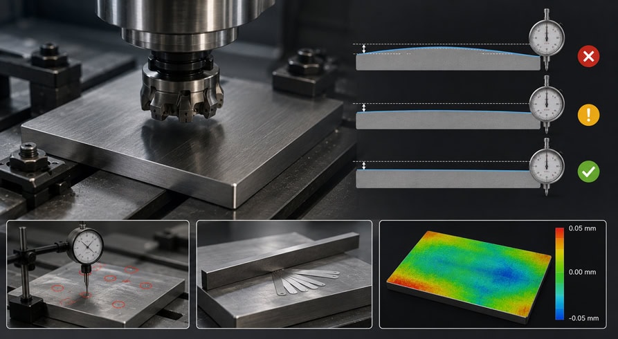
You need to understand the concept of flatness in CNC machining. This knowledge is essential for producing high-quality and precise components. Flatness in CNC machining indicates how closely a surface approaches a perfect plane. If you fail to apply the correct tolerance and measurement, you may encounter various issues. These problems can complicate assembly and reduce accuracy. Some common issues arising from poor flatness in CNC machining include:
Parts that rock during assembly, leading to uneven load distribution and potential failure
Leaks from sealing surfaces due to uneven contact pressure
Misalignment that results in premature wear and subpar performance of components
A clear understanding of flatness in CNC machining, along with appropriate engineering tolerances, is crucial for maintaining quality and control. This guide will assist you in managing flatness effectively and achieving improved results.
Key Takeaways
You need to know about flatness for good CNC parts. Bad flatness can cause problems when putting parts together. It can also make parts work worse.
Pick the best materials and machining ways to keep flatness. This stops parts from bending and helps them fit right.
Use the right tools like surface plates and dial indicators to check flatness. Good measurements help keep the parts high quality.
Talk clearly with suppliers about what flatness you need. Clear talking stops mistakes and makes sure parts are made right.
Use quality checks during the whole machining process. Checking often helps find problems early and keeps parts in tolerance.
OVERVIEW OF FLATNESS IN CNC MACHINING
WHAT IS FLATNESS IN CNC MACHINING
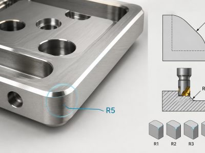
Flatness in cnc machining means how much a surface is not flat. You use flatness to see if a surface is even everywhere. Flatness tells you how much one surface can change from being flat. This is important because a part can look right in size but still not be flat enough. In cnc machining, you set flatness as the most a surface can move away from a flat line. You show this as a distance or a tolerance zone. This guide explains why flatness is important and how you can control it.
WHY FLATNESS MATTERS FOR MACHINED PARTS
You must care about flatness to make good parts. Flatness changes how parts fit and work together. If you do not check flatness, you might get leaks, rocking parts, or bad seals. These problems can make assemblies fail or not last long. Many things can change flatness in cnc machining:
The raw material and how flat it is at first
How accurate and clean your cnc machine is
How well your program works and how skilled the operator is
How you hold and clamp parts, which can add stress
Using stress relief steps to stop warping
You can get better flatness by picking good materials, using accurate machines, and following the best ways to make parts.
HOW FLATNESS AFFECTS QUALITY AND PERFORMANCE
Flatness is very important for the quality and how well machined parts work. When you keep flatness tight, parts seal well and share weight evenly. Bad flatness can cause leaks or bad contact right away. Over time, these problems can get worse and cause big failures. The table below shows how flatness tolerance problems can hurt performance:
Tolerance Issue | Immediate Impact | Long-Term Consequence |
|---|---|---|
Surface not flat enough | Poor seal, fluid/gas leaks | Reduced efficiency, potential system failure |
You keep your products working well and lasting longer by controlling flatness. This helps you make strong and high-quality cnc parts.
FLATNESS VS PARALLELISM AND STRAIGHTNESS
FLATNESS VS PARALLELISM IN CNC MACHINING
Flatness and parallelism are not the same thing. Flatness checks if a surface is smooth and has no bumps. Parallelism shows how one surface matches another called a datum. You do not need a datum to check flatness. But you must use a datum for parallelism. Flatness is for making one surface as flat as possible. Parallelism is for keeping two surfaces the same distance apart everywhere.
Here is a table that shows the main differences:
Feature | Definition | Reference to Datum |
|---|---|---|
Flatness | Checks how much a surface is not perfectly flat. | No |
Parallelism | Makes sure a surface stays lined up with a datum. | Yes |
Straightness | Checks if a line is straight and not wavy. | No |
FLATNESS VS STRAIGHTNESS
Flatness and straightness sound alike but are not the same. Flatness checks a whole surface to see if it is even. Straightness checks just a line or edge to see if it is smooth. Use straightness when you want a line to be straight. Use flatness when you want a surface to be level.
Tip: If you want a part to sit flat, check flatness. If you want an edge to fit tight, check straightness.
WHEN TO SPECIFY EACH TOLERANCE
You need to pick the right tolerance for your cnc project. Use flatness if you want a surface to seal or fit well. Use parallelism if you want two surfaces to stay the same distance apart. Use straightness if you want a line or edge to be smooth. Good tolerances help you stop leaks, rocking, or bad fits. When you know these differences, you can make better choices and get better parts from cnc machining.
FLATNESS TOLERANCE IN CNC MACHINING AND GD&T
GD&T FLATNESS SYMBOL EXPLAINED
The gd&t flatness symbol shows flatness on drawings. It looks like a parallelogram shape. You put it in the feature control frame. This symbol means a surface must stay between two parallel planes. These planes set the flatness tolerance limit. You do not need a datum for flatness checks. You only check the surface itself. When you follow geometric dimensioning and tolerancing rules, you keep the surface flat. The symbol helps guide manufacturing and machining teams.
Tip: Always look at the flatness symbol in the guide before you start machining. This helps you avoid mistakes and keeps your parts within tolerance.
FLATNESS TOLERANCE ON ENGINEERING DRAWINGS
You see flatness on drawings in the feature control frame. Flatness in a drawing shows the most a surface can move from being flat. You set the tolerance limit by marking the flatness symbol and value. This value tells how much the surface can move between two parallel planes. Flatness on drawings controls machining tolerances and keeps parts within quality standards. Flatness in cnc machining helps stop warping and stress problems. You must follow geometric dimensioning and tolerancing rules to keep parts precise.
Here is how you usually show flatness on drawings:
Put the flatness symbol in the feature control frame.
Write the tolerance limit value next to the symbol.
Make sure the surface stays within the set tolerance.
STANDARD FLATNESS TOLERANCES AND LIMITS
You must know standard flatness tolerances to keep parts within quality limits. Flatness tolerances are important in cnc machining. You use gd&t to set these limits. Flatness issues can come from material stress or clamping forces during machining. Thin-walled or plastic parts need tighter tolerance limits. Warpage can happen after machining, so you must check flatness often. Flatness on drawings guides manufacturing and keeps parts within precision standards.
Here is a table showing common flatness tolerance limits for cnc machining:
Material | Standard Flatness Tolerance Limit | Typical Machining Tolerances |
|---|---|---|
Aluminum | 0.05 mm | 0.02 - 0.1 mm |
Steel | 0.03 mm | 0.01 - 0.08 mm |
Plastics | 0.10 mm | 0.05 - 0.15 mm |
You must follow these tolerance limits to keep parts flat and within machining tolerances. This guide helps you understand flatness in cnc machining and how to use geometric dimensioning and tolerancing for better quality.
CNC FLATNESS TOLERANCE REFERENCE TABLE
FLATNESS TOLERANCE VALUES FOR COMMON MATERIALS
It is important to know how materials affect flatness. Every material acts differently when you machine it. Some metals stay flat without much trouble. Plastics can bend or twist more easily. You need to pick the right flatness tolerance for your project. This helps you stop problems during manufacturing.
Here is a table that lists flatness tolerances for common materials:
Material | Flatness Tolerance (mm) | Notes |
|---|---|---|
Aluminum | 0.02 - 0.05 | Good for most applications |
Steel | 0.01 - 0.03 | High strength, stays flat |
Stainless | 0.01 - 0.04 | Resists corrosion |
Brass | 0.02 - 0.06 | Easy to machine |
Plastics | 0.05 - 0.10 | Can warp, needs care |
Tip: Check the flatness tolerance for your material before machining. This helps you plan and get better results.
TYPICAL CNC MACHINING TOLERANCE RANGES
You need to set the right tolerances for cnc jobs. Tolerances decide how much a part can change from its shape. Tight tolerances give you more accuracy. Loose tolerances can save time but may lower quality. You should match tolerances to your part and how you make it.
Here are some common tolerance ranges in machining:
General machining: 0.05 mm to 0.10 mm
Precision machining: 0.01 mm to 0.03 mm
High-precision work: 0.005 mm or less
Use these ranges as a guide. Always check your drawings and talk to your team. Good communication helps you meet flatness and other tolerances. This keeps your cnc parts strong and dependable.
HOW TO MEASURE FLATNESS IN CNC MACHINING
FLATNESS MEASUREMENT TOOLS
You need special tools to check flatness. These tools help you see if a surface is flat enough. Some common tools are:
Surface plates: You put your part on a flat plate and look for gaps.
Dial indicators: You move the indicator over the surface to find bumps or dips.
Height gauges: You measure points on the surface from a flat base.
Coordinate Measuring Machines (CMM): These machines measure flatness very accurately.
Laser scanners: You scan the surface quickly for detailed results.
Each tool gives you different accuracy. Pick the tool that fits your part size and quality needs.
FLATNESS MEASUREMENT METHODS
There are several ways to measure flatness. The simplest way uses a feeler gauge and a surface plate. You slide the gauge under the part to find uneven spots. For better accuracy, use a dial indicator or a CMM. These tools let you measure many points. Laser scanners show the whole surface.
When you measure, follow these steps:
Clean the part and the tool.
Put the part on the reference surface.
Measure at different spots.
Write down the highest and lowest numbers.
Check if the difference fits your flatness tolerance.
Tip: Always measure in a steady place. Changes in temperature can change your results.
INTERPRETING MEASUREMENT RESULTS
You need to know how to read your measurements. This helps you see if your part meets flatness requirements. ASTM E1155 gives a standard way to measure and report flatness. You should:
Set the main plane for your part.
Use your tool to make a measured plane.
Look for bad data and ignore it.
Use geometry controls to add flatness from the GD&T tab.
Flatness is the space between two parallel planes.
If your measurements are within the set tolerance, your part is good. If not, you may need to change your machining process. Good measurements help you keep quality high and reach your manufacturing goals.
CONTROLLING FLATNESS IN CNC MACHINING
MATERIAL PROPERTIES AND MACHINING EFFECTS
You need to know how materials change flatness. Every material has its own chemical makeup. This decides how steady it stays when you machine it. Hard materials like aluminum and steel can bend more than soft ones. Some materials, like ABS and fiberglass, keep their shape better. Plastics such as nylon need extra care to stay flat. When you plan your process, think about these differences. You also need to check how exact your machine is. Pick the right tool and plan the order of steps. Inside stress and outside forces, like cutting and heat, can change your part’s shape. If you use the best tools and set good rules, you can keep tight tolerances.
Hard materials can bend more during machining.
Stable materials like ABS and fiberglass stay flat better.
Tool choice and step order change the final part.
Cutting and heat can make parts change shape.
FIXTURING AND WORKHOLDING STRATEGIES
You must hold your part the right way to keep it flat. Good fixturing stops the part from moving or bending. Use the right clamp force so you do not bend the part. Design your part so it is easy to clamp. Hydraulic fixtures give even pressure and help stop bending. Vacuum chucks are good for soft parts and lower the chance of bending. Always check the clamp force when you set up. Try a light cut first to see if it shakes. Custom jigs with three points can lower inside stress and help you keep tight tolerances.
Use even clamp force.
Pick hydraulic or vacuum fixtures for special parts.
Test for shaking before you cut all the way.
Use custom jigs for better holding.
THERMAL DISTORTION AND RESIDUAL STRESS
Heat and stress can change your part’s shape after you machine it. When you take a part out or change its temperature, it can bend or twist. This is called distortion. Even if your part looks good at first, it might lose flatness later. You need to plan your steps to lower this risk. The table below shows how stress and heat can change your part:
Evidence Description | Impact on Flatness |
|---|---|
Residual stresses can make parts bend when you take them out or change the temperature. | Causes bending, twisting, or loss of flatness, especially in thin or odd-shaped parts. |
Parts can change shape even if they leave the machine within tolerance. | Shape can shift and hurt flatness and size. |
Knowing about distortion helps you plan your work. | Lowers the chance of parts bending or warping after machining. |
CUTTING PARAMETERS AND TOOL PATH OPTIMIZATION
You can get better flatness by picking the right cutting rules and tool paths. The way you cut changes how much force and heat you make. Using the shortest tool gives you better accuracy and less tool bending. The right tool coating, flute shape, and size also help you meet your goals. You can use different ways to cut, like profile, pocketing, adaptive clearing, or parallel finish. Each way has good and bad points. The table below shows some common ways:
Strategy | Purpose | Pros | Cons |
|---|---|---|---|
Profile | Cut along an edge | Simple, fast | Not for big cuts |
Pocketing | Remove material inside | Good for holes | May leave marks |
Adaptive Clearing | Rough cut with steady load | Fast, long tool life | Needs special software |
Parallel Finish | Smooth 3D surfaces | Great finish | Slow |
When you set the right rules, you get a better surface and keep tight tolerances. This helps you make strong cnc parts that fit your needs.
HOW TO REDUCE AND IMPROVE FLATNESS IN CNC MACHINING
PROCESS OPTIMIZATION TECHNIQUES
You can make flatness better by using smart steps in cnc machining. First, pick materials that do not warp and do not change much with heat. Hold your workpiece tightly so it does not move or shake. Change how fast you cut and feed to lower heat and stop the tool from bending. Cut your parts in steps so you do not remove too much at once. After you finish cutting, use grinding or stress relief to take away inside stress and make flatness better.
Here are some ways to help your process:
Pick strong materials to keep parts flat.
Use good fixtures to hold parts still.
Change cutting rules to stop heat from building up.
Cut in steps to avoid big changes.
Use grinding or annealing after machining.
Tip: Check your tools often and use a flat surface to keep your results right.
PRECISION MACHINING STRATEGIES
You need special ways to get tight tolerances and good quality. Precision milling makes flat surfaces when you use sharp tools and set the right rules. Grinding is another way to get great flatness. It uses a rough wheel and needs careful picking of wheels and coolants. Heat treatment helps take away inside stress, but you must control it so you do not make new bends. These ways help you reach the flatness your project needs.
QUALITY CONTROL AND INSPECTION METHODS
Quality control and checking are important for keeping flatness within limits. You should use a surface plate and feeler gauge or height gauge to find uneven spots. Coordinate measuring machines (CMM) give very exact flatness numbers with a probe. Optical checks, like laser scanning and interferometry, show you the whole surface in detail. Use these tools at different times in making parts to find problems early and keep your parts within limits.
Surface plate checks for gaps and bumps.
CMM gives exact flatness numbers.
Optical checks show the whole surface.
Note: Good quality control and regular checks help you make strong cnc parts and keep high standards.
DESIGN GUIDELINES FOR BETTER FLATNESS
DESIGNING PARTS FOR FLATNESS CONTROL
You can make flatness better by designing smart parts. Try not to use big, thin flat faces. These faces can bend or twist during machining. Keep important faces separate from regular ones. This lets you control flatness where it matters most. Always say if a face is for mounting or sealing. This tells the machinist which face needs to be flat. Before making parts, talk about how the material acts. Some materials, like aluminum, change shape more with heat. You need to plan for this early.
Tip: Warping depends on how much a surface moves from a reference plane. Use ways to lower warping, especially with materials that expand easily.
TOLERANCE STACK UP CONSIDERATIONS
You need to think about how tolerances add up in your design. If you use many tight tolerances, making parts gets harder and costs more. Follow these steps to help control flatness and keep quality high:
Remove inside stress from your part.
Machine both sides in small steps.
Use new and sharp cutting tools.
Mix rough and finish machining for better results.
Pick the best way to clamp your part.
Drill holes before you mill surfaces.
These steps help you keep flatness within your goal and stop problems during cnc machining.
COMMUNICATING REQUIREMENTS WITH SUPPLIERS
Talking clearly with your supplier is important for good flatness. Always show part details on your drawings. This stops mistakes that can hurt how parts work or cause delays. Make sure you know the difference between flatness and parallelism. Use the right callouts in your drawings. Use GD&T to explain what you need. This helps your supplier know exactly what you want. Good communication gives you better parts and higher precision in your cnc work.
FAQ
WHAT IS FLATNESS TOLERANCE IN CNC MACHINING
Flatness tolerance is a rule for surfaces. It tells how much a surface can move from being flat. You use flatness tolerance in cnc machining so parts fit and work well. ISO 2768 and ASME Y14.5 are standards for flatness. These standards help you keep parts within limits. If you follow these rules, your parts will be reliable.
ISO 2768: Sets general tolerances, including flatness.
ASME Y14.5: Gives rules for geometric dimensioning and tolerancing, including flatness.
Here is a table that shows how much a surface can change based on its size:
Nominal Length (mm) | Permissible Flatness Deviation (mm) |
|---|---|
Up to 100 | 0.1 |
100 to 300 | 0.2 |
300 to 1000 | 0.3 |
HOW IS FLATNESS MEASURED
You check flatness by seeing how much a surface moves from a flat plane. You can use tools like a surface plate, dial indicator, or coordinate measuring machine. Put your part on a flat surface and look for bumps or gaps. For more accuracy, use a CMM or laser scanner. These tools show if your part meets the flatness tolerance in your design.
Tip: Clean your part and tools before measuring. Dirt or dust can change your results.
WHAT IS THE DIFFERENCE BETWEEN FLATNESS AND PARALLELISM
Flatness checks if one surface is smooth and even. You do not need another surface for flatness. Parallelism compares two surfaces to see if they stay the same distance apart. You always use a reference surface, called a datum, for parallelism. Both are important in manufacturing, but you use them for different reasons.
HOW CAN FLATNESS BE CONTROLLED IN CNC MACHINING
You control flatness in cnc machining by picking the right material. Use good fixturing and set the best cutting rules. Watch for heat and stress during manufacturing. Use sharp tools and cut in small steps to lower bending or warping. Always check your parts during and after machining to keep flatness within your set tolerance. Good control helps you reach high precision and keeps your products strong.
You help keep flatness in control during cnc machining. Always check your tolerances before you start. Use the correct tools to measure flatness. Good tolerance control stops problems in cnc projects. Choose the best steps for making your parts. Tell your team what flatness you need. These actions give you strong and dependable results.
Check tolerances before you begin.
Use proper tools to measure flatness.
Talk with your manufacturing team.