 LKprototype
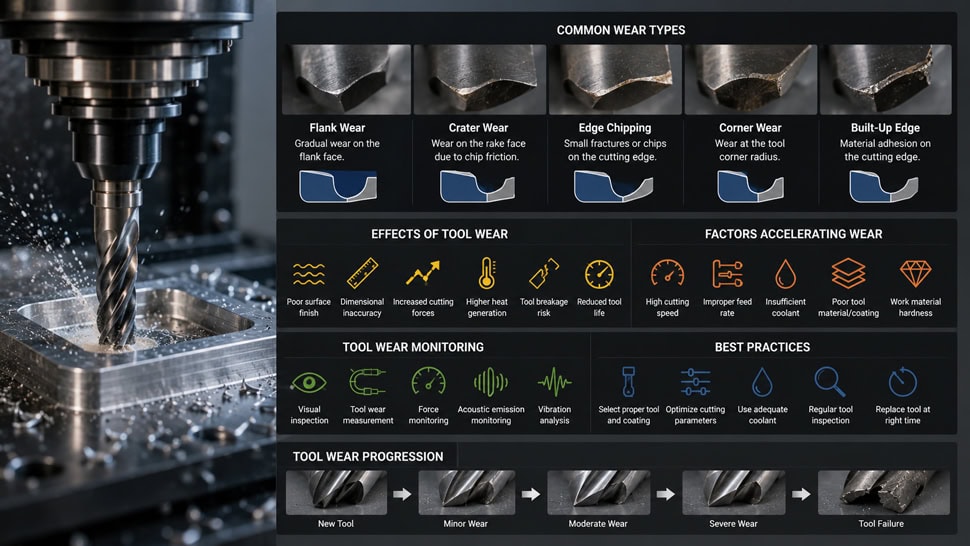
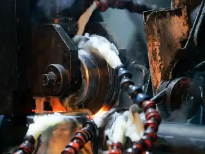
You often see tool wear in cnc machining when you cut parts. This means the cutting tool slowly gets less sharp or loses its shape. Tool wear can change how your machines work. You may see rougher surfaces or parts that do not fit right. If you know about tool wear, you can keep your machines working longer and save money. New studies show how tool wear changes your costs:
Evidence Description | Impact on Production Costs |
|---|---|
Tool wear prediction technology can stop tool damage and make chip speed better. | Brings big savings in production costs. |
Watching tool wear uses more material and energy and can stop production sometimes. | Makes production work better and lowers extra maintenance costs. |
Machinists, engineers, and even skilled hobbyists gain from knowing how to find and handle tool wear. You can make better products and waste less if you look for signs early.
Key Takeaways
Learn about tool wear to help machines work better and save money. Finding problems early keeps the work good.
Watch cutting speed, feed rate, and depth of cut to lower tool wear. Set these right to make tools last longer.
Pick the best tool materials and coatings to make them stronger. Hard materials like carbide and special coatings help tools last longer.
Check tools often for wear types like flank wear and crater wear. Finding wear early stops expensive machine stops.
Do regular maintenance and use smart tool management. This helps stop surprise problems and keeps production running well.
OVERVIEW OF TOOL WEAR IN CNC MACHINING
WHAT IS TOOL WEAR IN CNC MACHINING
When you use a cutting tool in cnc machining, the tool slowly loses its sharpness and shape. This process is called tool wear in cnc machining. You see this happen because of friction, heat, and the pressure between the tool and the material. Over time, the tool cannot cut as well as before. You can find different types of tool wear in cnc machining. Here is a table that explains some common types:
Type of Tool Wear | Description |
|---|---|
Abrasive Wear | Happens when hard particles in the material scratch and wear down the tool. |
Flank Wear | Forms along the side of the tool, making the edge dull. |
Crater Wear | Appears as a small pit on the tool’s face where chips slide over it. |
Adhesion Wear | Occurs when material sticks to the tool and pulls tiny pieces away. |
WHY TOOL WEAR MATTERS FOR PRODUCTIVITY AND QUALITY
You need to watch for tool wear because it can change how your cnc machining works. When a tool wears out, you may notice these problems:
Cutting forces go up, so your machine works harder and less efficiently.
The tool and the part get hotter, which can damage both.
Parts may not fit right, so you might need to fix or throw them away.
If you keep your tools in good shape, you make better parts and save time and money.
TOOL WEAR VS TOOL LIFE EXPLAINED
You might hear people talk about tool wear and tool life. These are not the same. Tool wear means the tool is getting worse because of use. Tool life tells you how long the tool can work before you must replace it. Here is a table to help you see the difference:
Concept | Definition |
|---|---|
Tool Wear | The cutting tool gets damaged from friction and other forces during machining. |
Tool Life | The amount of time or material a tool can cut before you need a new one. |
Tip: If you understand both tool wear and tool life, you can plan better and keep your cnc machining running smoothly.
CAUSES OF TOOL WEAR IN CNC MACHINING
CUTTING SPEED FEED RATE AND DEPTH OF CUT
You control how fast the tool moves and how much material it cuts with cutting speed, feed rate, and depth of cut. These settings change how quickly tool wear in cnc machining happens. If you use a high cutting speed, you create more heat. This heat can damage the tool and make it wear out faster. Feed rate also matters. When you increase feed rate, you finish jobs quicker, but you put more stress on the tool. Depth of cut affects how much force the tool faces. If you cut too deep, you risk breaking the tool. You can see the main effects below:
Higher cutting speed increases heat and speeds up tool wear.
High feed rate boosts production but can cause more tool damage.
Deep cuts raise cutting forces and may lead to tool fracture.
Tip: You get the best tool life when you balance cutting speed and feed rate for your material.
MATERIAL HARDNESS AND ABRASIVENESS
The hardness of the material you machine changes how fast your tool wears out. Hard materials like hardened 304 stainless steel can make tool wear rate jump by 50%. When you cut hard metals, you need to slow down cutting speed to protect your tool. High-pressure contact breaks off tiny tool particles, which speeds up wear. Abrasive materials scratch the tool surface and make it dull faster.
Aspect | Description |
|---|---|
Material Hardness | Harder materials lead to rapid wear of cutting tools due to increased mechanical wear. |
Thermal Conductivity | Low thermal conductivity in hard materials decreases bond strength in tool material at high temps. |
Pressure and Friction | High-pressure contact causes small particles of the tool to break off, accelerating wear. |
COOLANT AND LUBRICATION CONDITIONS
You can slow tool wear by using the right coolant and lubrication. High-pressure coolant helps keep the tool cool and reduces wear compared to dry or flood cooling. Minimum quantity lubrication (MQL) lowers friction and removes chips. This stops chips from being cut again and keeps the tool sharp. Good cooling and lubrication make machining smoother and extend tool life.
THERMAL AND MECHANICAL STRESSES
Heat and force during machining cause tool wear. When you use high feed rates or deep cuts, you create more friction and heat. This leads to abrasive and adhesive wear. If you keep cutting speed high but feed rate low, you can reduce flank wear and get longer tool life. Too much heat or force can crack or chip the tool, making it fail early.
Evidence Description | Impact on Tool Wear |
|---|---|
Flank wear progression is influenced by cutting speed, feed rate, and depth of cut. | Increased feed rate and depth of cut lead to stronger friction, higher cutting temperatures, and reduced tool life. |
Higher cutting speeds reduce VB, especially at low feed rates. | Optimal tool life is achieved with high cutting speeds and low feed rates. |
VB increases sharply with higher feed rates and depth of cut. | Higher cutting loads and heat generation contribute to increased wear. |
TYPES OF TOOL WEAR IN CNC MACHINING
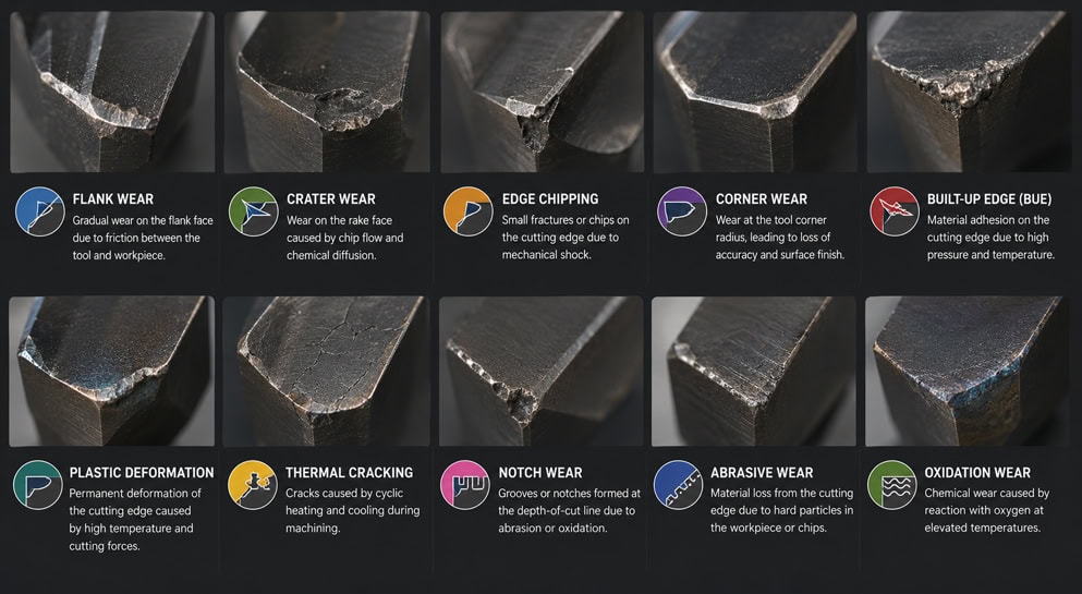
Understanding the types of tool wear in cnc machining helps you make better decisions in your shop. When you recognize types of tool wear, you can fix problems early and keep your machines running longer. Here are the main types you will see:
FLANK WEAR
Flank wear is the most common form of cutting tool wear. You will notice it as the edge of your tool becomes dull and worn down. This wear happens slowly and evenly along the cutting edge. At lower cutting speeds, abrasive and adhesive forces cause most of the wear. When you use higher speeds, heat increases and diffusion wear becomes more important. Flank wear usually looks like a smooth, even line along the tool’s edge. Sometimes, the workpiece material smears on the edge, making the wear scar look bigger. If you machine tough materials, you may see rapid flank wear.
Flank wear is gradual and predictable.
It is often the most desirable type because you can plan for it.
CRATER WEAR
Crater wear forms on the top surface of your tool, where chips slide over it. This type of wear creates a small pit or depression, called a crater. High cutting speeds and chip flow cause this problem. If you do not watch for crater wear, your tool can fail quickly.
Cause of Crater Wear | Effect on Tool |
|---|---|
High cutting speeds | Erosion leading to depressions on the rake face |
Chip flow over surface | Formation of craters and potential tool failure |
Abrasive materials | Accelerated wear and chipping of the tool's edge |
Crater wear often results from chemical reactions and high temperatures during fast machining.
BUILT UP EDGE FORMATION
Built-up edge (BUE) happens when the material you are cutting sticks to the tool’s edge. You will see this most with soft metals like aluminum or copper. The built-up material can change the shape of your tool and affect the finish of your part. Cutting speed and the use of coolants or lubricants can make BUE more or less likely.
BUE forms when material welds to the tool edge.
It can break off and damage your part’s surface.
CHIPPING AND FRACTURE
Chipping and fracture are sudden types of tool wear. You might see small pieces break off the cutting edge, or the tool may crack. This usually happens if you use too much force, cut too deep, or machine very hard materials. Chipping and fracture can end a tool’s life quickly, so you need to watch for them.
Tip: If you check your tools often, you can spot these problems before they cause bigger issues.
By learning to recognize types of tool wear, you can improve your machining results and avoid costly downtime.
TOOL WEAR MECHANISMS AND FAILURE MODES
When you use CNC machines, tools can wear out or break in different ways. If you know how this happens, you can stop tool problems before they get worse. Here are the main types you should know about:
ABRASIVE WEAR
Abrasive wear happens when hard bits in the workpiece scratch your tool. This scratching takes away tiny pieces from the tool’s surface. You see this most when you cut hard materials. If you do not check your tools often, abrasive wear can make them fail.
Factor | Description |
|---|---|
Mechanical Forces | Friction and pressure from cutting cause tool surface loss. |
Abrasion and Chipping | Hard materials make the tool chip and wear faster. |
High-Pressure Contact | Small tool particles break off, reducing tool life. |
You can slow down abrasive wear by picking the right tool material and using the best cutting speed.
ADHESIVE WEAR
Adhesive wear happens when your tool and the workpiece stick together in tiny spots. When these spots pull apart, they take small pieces of the tool with them. This makes the cutting edge weaker and can break the tool.
Tiny bonds form between the tool and workpiece.
When these bonds break, the tool loses material.
The part’s surface may look rougher.
Key Findings | Description |
|---|---|
Adhesive Wear Mechanism | Main cause of tool failure in metal cutting. |
Impact on Production | Raises costs and lowers productivity. |
Material Interaction | Tool and workpiece bond and separate, causing tool damage. |
You should watch for adhesive wear to keep your tools sharp and your parts smooth.
DIFFUSION WEAR
Diffusion wear is a problem when things get very hot. When you cut fast, atoms from your tool move into the chip. This makes the tool weaker and can cause it to break. You see this most with carbide tools and when cutting tough metals.
Type of Wear | Description |
|---|---|
Diffusion Wear | Atoms from the tool move into the chip, reducing tool strength and life. |
If you cut slower or use coolant, you can lower diffusion wear.
OXIDATION WEAR
Oxidation wear happens when heat and air cause a chemical change on your tool’s surface. This change makes oxides that weaken the tool. You see more oxidation wear when you cut fast or machine ductile iron.
Oxygen in the tool goes up after cutting, showing chemical wear.
Oxidation of things like boron and carbon proves this wear type.
Tools with more binder can have worse oxidation wear.
If you control heat and use coated tools, you can slow oxidation wear and stop early tool failure.
Note: Flank wear, crater wear, built-up edge, microchipping, thermal cracking, and plastic deformation are also common tool failure modes. Flank wear is the easiest to predict and manage.
If you learn about these wear types, you can make better choices and keep your CNC tools working longer.
EFFECTS OF TOOL WEAR ON MACHINING PERFORMANCE
SURFACE FINISH QUALITY
You notice changes in surface finish when your cutting tool wears out. A sharp tool slices material cleanly, but a worn tool struggles to shear the material. This leads to rough or uneven surfaces. Built-up edge (BUE) forms when material sticks to the tool, making the surface even rougher. Vibrations from a dull tool can also make the finish worse. You want smooth surfaces for parts that fit together well and look good. Poor surface finish increases friction between parts, reduces fatigue life, and affects the appearance.
Tool wear causes rough or uneven surfaces.
Built-up edge makes the texture worse.
Vibrations from worn tools degrade surface quality.
Poor finish increases friction and reduces part life.
Tip: Check your tools often to keep surface finish quality high.
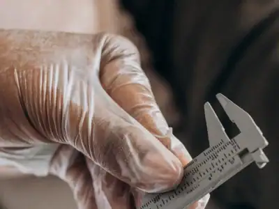
DIMENSIONAL ACCURACY AND TOLERANCE
Dimensional accuracy means your parts match the size you want. Tool wear changes the shape of your cutting tool. This leads to parts that do not meet your measurements. If the tool diameter gets smaller, your features may turn out too small. Dull edges need more force, which can push the tool or workpiece out of place. This causes errors in size and shape. You must watch for tool wear to keep your parts within tolerance.
Tool wear changes tool geometry, causing size variations.
Smaller tool diameter makes features smaller than planned.
Dull edges increase force, leading to deflection and errors.
Note: Keeping tools sharp helps you maintain tight tolerances.
PRODUCTION EFFICIENCY AND COST
Tool wear affects how fast you can make parts and how much money you spend. When tools wear out, you need to stop the machine to change them. This slows production. Worn tools also make more scrap parts, which wastes material and time. You spend more on new tools and repairs. If you manage tool wear, you boost efficiency and lower costs.
Impact of Tool Wear | Result |
|---|---|
Frequent tool changes | More downtime |
Increased scrap rate | Higher material waste |
More tool purchases | Higher expenses |
Keeping tool wear under control helps you save time and money. 😊
TOOL WEAR MONITORING AND MEASUREMENT METHODS
VISUAL INSPECTION AND MICROSCOPE ANALYSIS
You can check tools by looking at them. This helps you find wear, chips, or cracks. Machinists use magnifying glasses or microscopes to see small changes. If you have experience, you can spot problems faster. Sometimes, tiny cracks or edge damage are hard to see. Machine vision systems use cameras to find these issues. These cameras show more details and help you catch problems early. Automatic tool monitoring systems can be as good as microscopes. They only make a few mistakes. Non-contact methods let you check tools without stopping the machine.
Visual inspection needs skill and takes time.
Machine vision makes tool checks faster and more accurate.
Cameras help you find wear and keep machines running.
TOOL WEAR MEASUREMENT TECHNIQUES
There are many ways to measure tool wear. Each method helps you check tools and find problems. Some common ways are vibration analysis, acoustic emission, force measurement, and temperature checks. You can also use power meters and image systems. Machine learning finds patterns in the data. Here is a table that shows how each method works:
Method | Principle | Implementation |
|---|---|---|
Vibration Analysis | Tool wear changes vibration patterns | Use accelerometers to track frequency changes |
Acoustic Emission Monitoring | Sound reveals tool condition | Sensors record sound; high noise means more wear |
Force Measurement | Cutting forces rise with wear | Dynamometers measure force; increases show wear |
Temperature Monitoring | More wear means more heat | Use infrared sensors or thermocouples to check temperature |
Tool Wear Imaging | Images show surface changes | Optical systems capture and analyze tool images |
Power Consumption Monitoring | More power means more wear | Power meters track energy use; increases signal wear |
Machine Learning | Finds wear patterns in data | Models process sensor data for tool monitoring |
Cutting Force Ratio Analysis | Force ratios change with wear | Sensors measure forces in different directions |
You can use more than one method for better results. Using several ways helps you find tool wear and keeps your work reliable.
USING SENSORS AND CNC MONITORING SYSTEMS
Sensors and CNC monitoring systems tell you about tool condition right away. You can use sensors to check vibration, sound, force, and temperature. These systems help you find tool wear before it causes trouble. Machine learning looks at sensor data and predicts when a tool will break. This lets you plan repairs and avoid stopping work. Modern CNC machines use sensors and cameras for fast tool checks. You can fix problems as soon as you see them. Studies show that checking tools all the time keeps parts accurate and machines working.
Study | Contribution |
|---|---|
Wang et al. | Machine learning helps predict tool wear better. |
Keneng Hardware | Machine learning finds tool wear for planned repairs. |
Tech Forum Journal | Online tool checks keep part quality and work going. |
JLCCNC | Sensors and cameras allow quick tool checks and fixes. |
Tip: Use CNC monitoring systems to keep your shop running well and your tools in great shape. 😊
HOW TO EXTEND TOOL LIFE IN CNC MACHINING
OPTIMIZING CUTTING PARAMETERS
You can make your tools last longer by setting the right cutting parameters. Spindle speed, feed rate, and depth of cut all affect how fast your tool wears out. If you use the wrong settings, your tool gets too hot or faces too much stress. This makes it wear out quickly. Adjust these settings based on the material you are cutting. For hard materials, use lower speeds and moderate feed rates. For finishing, try higher speeds with lighter cuts.
Cutting speed is one of the most important factors. If you increase speed, you can finish jobs faster, but you also create more heat. Too much heat shortens tool life. Always look for the best speed for your job.
SELECTING THE RIGHT TOOL MATERIAL AND COATING
The material and design of your tool matter a lot for tool longevity. Choose strong materials like carbide for tough jobs. The right tool coating can protect your tool from heat, friction, and wear. Coatings like titanium nitride or aluminum oxide add a hard layer to the tool. This layer helps resist abrasion and oxidation. Tool coating also keeps the tool cooler and stops chips from sticking. If you pick the best tool coating for your job, you will see less wear and better performance.
Tool Material or Coating | Benefit for Tool Life |
|---|---|
Carbide | High strength and wear resistance |
Titanium Nitride Coating | Reduces friction and heat |
Aluminum Oxide Coating | Protects against oxidation and wear |
IMPROVING COOLING AND LUBRICATION
Coolants and lubricants help your tool stay cool and reduce friction. When you use enough coolant, you stop the tool from overheating. Lubrication also helps chips move away from the cutting area. This keeps the tool sharp and clean. You can use high-pressure coolant or minimum quantity lubrication for better results. Good cooling and lubrication work with the tool coating to give you longer tool life.
Use coolants to lower heat.
Apply lubricants to reduce friction.
Make sure chips do not build up on the tool.
REDUCING CUTTING FORCES AND HEAT GENERATION
You can extend tool life by lowering the forces and heat during machining. Use sharp tools and keep them in good shape. Choose the right tool path to avoid heavy cuts. A stable fixture and a rigid tool holder help reduce vibrations. Shorter gauge length also makes the tool more stable. When you control these factors, you protect the tool coating and improve tool longevity.
Tip: Always check your setup before starting. A stable machine and the right settings help your tools last longer. 😊
TOOL LIFE OPTIMIZATION STRATEGIES
PREVENTIVE MAINTENANCE AND TOOL MANAGEMENT
You can make CNC tools last longer with preventive maintenance and smart tool management. If you check your machines often, you find problems early. This helps you fix issues before your machine stops working. You plan repairs and replacements ahead of time. This means you do not get surprised by sudden breakdowns. Regular tool care helps you make better parts and waste less material. You save money because you do not need to buy new tools as much.
Here is a table showing how preventive maintenance and tool management help:
Benefit | Description |
|---|---|
Reduced Downtime | You stop unexpected machine failures and keep production going. |
Improved Work Completion Rates | Machines work better, so you finish jobs faster. |
Extended Machine Tool Life | Tools last longer, so you replace them less often. |
Maximized Production Time | Machines run longer without stopping, so you make more parts. |
Reduced Scrap and Rework | You keep quality high and waste low. |
Lowered Setup and Adjustment Time | You spend less time setting up machines. |
Planned Replacement Costs | You can plan for new parts and tools. |
Increased Profitability | More uptime means more profit for your shop. |
Well-Maintained Service Records | Good records help you plan future maintenance. |
Using tool life management can help tools last longer.
Proactive maintenance lowers your costs.
Changing parameter settings keeps tools working well.
ADVANCED TOOLING TECHNOLOGIES
You can use advanced tooling technologies to get better machining results. Modern tools have special coatings that protect them from heat and wear. Some tools have smart sensors that tell you when they need to be replaced. You can try new tool designs that cut faster and last longer. These technologies help you make parts with better quality and less waste.
Tip: Try coated tools or sensor-equipped tools to make your shop work better. 🛠️
BALANCING COST AND TOOL PERFORMANCE
You need to balance cost and tool performance for the best results. Cheap tools may wear out fast and cause more downtime. High-quality tools cost more but last longer and make better parts. You should look at how much you spend on tools and how much you save by making fewer mistakes. Good planning helps you pick the right tools for your jobs.
Note: Buying quality tools and doing regular tool maintenance saves money over time.
TOOL WEAR VS TOOL LIFE COMPARISON
KEY DIFFERENCES BETWEEN TOOL WEAR AND TOOL LIFE
You need to know the difference between tool wear and tool life. Tool wear means your cutting tool gets damaged or dull as you use it. Tool life tells you how long your tool can work before you must replace it. Tool wear happens every time you cut a part. Tool life ends when the tool cannot cut well anymore. You can see tool wear in many ways, like a dull edge or a chipped corner. Tool life is a measure of time or the number of parts you make before changing the tool.
Remember: Tool wear is about the process. Tool life is about the total time your tool lasts.
HOW TOOL WEAR AFFECTS TOOL LIFE
Tool wear shortens tool life. If you see more wear, your tool will not last as long. When you use the wrong speed or cut hard materials, tool wear happens faster. This means you must change tools more often. If you control tool wear, you can make your tools last longer. You should check for all types of tool wear to keep your tools working well. Good care and the right settings help you get the most tool life.
OPTIMIZATION STRATEGIES COMPARISON TABLE
You can use different strategies to manage tool wear and tool life. The table below shows how each strategy helps:
Strategy | Reduces Tool Wear | Extends Tool Life | Easy to Use |
|---|---|---|---|
✅ | ✅ | ✅ | |
Using Advanced Tool Coatings | ✅ | ✅ | ✅ |
Improving Cooling/Lubrication | ✅ | ✅ | ✅ |
Regular Tool Inspection | ✅ | ✅ | ✅ |
Using Sensors and Monitoring | ✅ | ✅ | ❌ |
Tip: Try simple strategies first. You can add advanced methods as you learn more.
BEST PRACTICES TO REDUCE TOOL WEAR IN CNC MACHINING
USING HIGH PERFORMANCE CUTTING TOOLS
You can lower tool wear by picking high performance cutting tools. These tools are made from strong stuff like carbide or ceramic. They are built to last longer and handle hard jobs. Special coatings like titanium nitride or diamond help protect the tool from heat and rubbing. These coatings also help you get smoother cuts and stop chips from sticking. If you want better machining, use tools made for your material.
Tip: Always look at the tool’s details before you start. High performance tools help you save both money and time.
OPTIMIZING TOOL PATH AND STRATEGY
You can make tools last longer by planning the tool path well. Make sure the tool moves smoothly and does not turn sharply. Use short tool paths when you can. This puts less stress on the tool and keeps it sharp. Try climb milling instead of regular milling. Climb milling lowers cutting forces and helps the tool last longer. You can use software to test the tool path before cutting. This lets you find problems early.
Tool Path Strategy | Benefit |
|---|---|
Smooth movements | Less tool stress |
Shorter paths | Reduced wear |
Climb milling | Lower cutting forces |
Simulation | Early problem detection |
IMPROVING MACHINE STABILITY
Machine stability is very important for tool wear. Make sure your machine is set up right. Use strong tool holders and fixtures to stop shaking. This keeps the tool steady while cutting. Check the spindle and bearings for any damage. Fix problems as soon as you see them. Stable machines help you cut more accurately and lower tool wear. You can also use dampers to soak up vibrations.
Note: Stable machines and tight setups help reduce tool wear. You get better results and your tools last longer.
😊 If you follow these best practices, you will have less tool wear and your machining will be more reliable.
FAQ
WHAT CAUSES TOOL WEAR IN CNC MACHINING
You see tool wear when your cutting tool loses its sharpness or shape. Many things can cause this. Hard materials scratch the tool. High cutting speeds make the tool hot. Not enough coolant lets the tool overheat. Too much force or vibration can chip the tool. If you use the wrong tool for the job, it will wear out faster.
Tip: Always check your cutting speed, feed rate, and coolant to slow down tool wear.
HOW CAN TOOL LIFE BE EXTENDED
You can make your tools last longer by following some simple steps:
Choose the right tool material and coating for your job.
Set the correct cutting speed and feed rate.
Keep your machine stable and well-maintained.
Inspect your tools often and replace them before they break.
A good setup helps you save money and make better parts.
WHAT ARE THE MAIN TYPES OF TOOL WEAR
You will find several types of tool wear in CNC machining. Here is a table to help you remember:
Type of Wear | What You See |
|---|---|
Flank Wear | Dull edge along the tool side |
Crater Wear | Pit or crater on the tool face |
Built-Up Edge | Material stuck to the tool edge |
Chipping/Fracture | Small pieces break off or cracks |
Each type affects your machining in a different way. You should watch for all of them.
HOW IS TOOL WEAR MEASURED
You can measure tool wear in a few ways:
Look at the tool with your eyes or a magnifier.
Use a microscope for small cracks or chips.
Check the size and finish of your parts.
Use sensors to track vibration, sound, or temperature.
Note: Regular checks help you catch tool wear early and keep your CNC machine running well.
You see tool wear from high cutting speeds, hard materials, poor cooling, and strong forces. Flank wear, crater wear, built-up edge, and chipping are common types. If you manage tool life, you improve quality and save money. Try regular checks, use high-performance tools, and optimize your settings.
Managing tool wear helps you make better parts, reduce waste, and keep your CNC machines running smoothly. 😊