Cylindricity is a vital aspect of GD&T that ensures an object is perfectly round and straight along its entire length. For components like shafts, bushings, and precision pins, accurate cylindricity is crucial for proper fit and efficient function. This article will break down what cylindricity involves, why it matters in manufacturing, and the best methods for measuring it accurately.
Key Takeaways
Cylindricity measures how closely a feature approximates a true cylinder, impacting fit, function, and component lifespan.
The cylindricity tolerance zone consists of two coaxial cylinders defining the acceptable boundaries for the feature’s surface.
Accurate cylindricity measurements are crucial for ensuring functionality in high-speed applications, reducing wear, and enhancing assembly performance.
Understanding Cylindricity
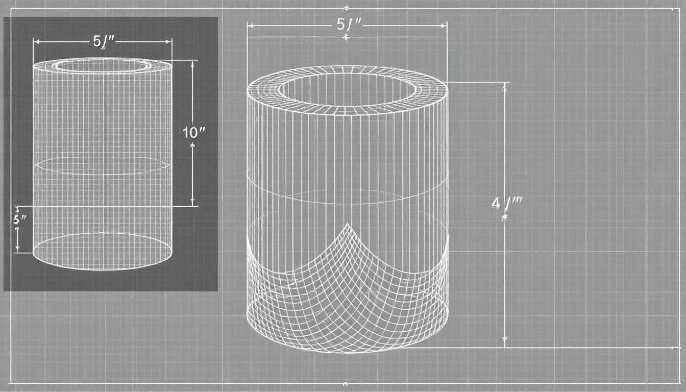
The concept of cylindricity in GD&T is used to determine the extent to which an object mirrors a perfect cylinder. Recognized as a type of form control, managing cylindricality involves ensuring that cylindrical elements retain uniform shape throughout their full length. This aspect of control becomes particularly essential for components like shafts and bushings that need exact circularity and alignment to function correctly within stringent tolerance limits.
For parts designed to fit together precisely, maintaining the integrity of a cylindrical profile is crucial. Take for example a pin meant to slide through a hole with minimal clearance—cylindricity guarantees that this pin remains evenly rounded and aligned along its axis, providing an ideal fit devoid of any slack or undue resistance. The implementation of this principle in GD&T not only heightens component functionality but also contributes toward diminishing wear over time.
When assessing cylindericity, it accounts for both straightness and flatness across the part’s entire length thus bringing it closer in resemblance to an ideal cylinder. To gauge this level of conformity accurately, one must secure the item along its central axis while rotating it. During rotation measurements are taken regarding surface deviations from true circular form. By adopting such thorough procedures for checking consistency against predetermined forms, one ensures superior operational efficiency and dependability within practical use cases for these mechanical features.
Cylindricity Tolerance Zone
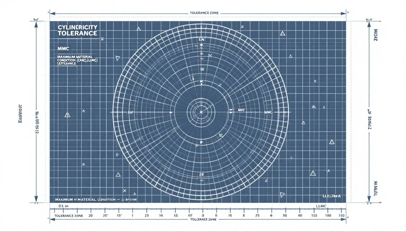
Cylindricity tolerances are confined within two concentric cylinders that cover the full length of a cylindrical feature, serving as boundary markers for where the entire surface must be situated. These concentric cylinders share an axis with the part’s cylindrical form to provide accurate regulation over its shape.
Within these boundaries, defined by the radial gap between both inner and outer cylinders, lies what is known as cylindricity tolerance limits. To satisfy this tolerance requirement, every point on the surface in question has to stay inside these specified radial confines—thus preserving the intended shape of said cylinder while preventing any anomalies which could interfere with how it operates or fits into other components.
The indication of cylindicty is noted in a feature control frame without consideration for material condition alterations because it strictly pertains to maintaining surface integrity. Through employing a symbol specific to cylindicity itself, emphasis is placed on achieving excellent roundness and straightness independently from size-based tolerances or variable conditions in materials. Thereby securing consistency along every segment of a cylinder’s exterior contour.
Cylindricity Feature Control Frame
The feature control frame for cylindricality is vital in GD&T, demonstrating the degree to which a cylindrical part adheres to the ideal form of a cylinder. This indicator is particularly prevalent in the automotive industry as it defines how dimensional specifications must be met to guarantee that parts are uniformly shaped across all three dimensions. By implementing this specific type of feature control frame, one can ensure that every aspect of the cylinder’s surface supports its designated function without any unwanted variation.
Notably, when dealing with cylindricity controls, there are no data references included within the feature control frame. The reason behind this omission is because controlling cylindricity addresses only the shape or form on a surface level while allowing greater leeway regarding diameter measurements. Such an approach provides advantages during production processes by upholding cylindrical accuracy without imposing overly restrictive size regulations.
Geometric Characteristic Block
The cylindricality symbol is represented by two parallel lines with an enclosed diameter symbol (), signifying the control of form along a feature’s entire length. This block depicting geometric characteristics is included in the feature control frame to convey that the whole surface of the cylindrical feature must conform to a specified tolerance zone.
When used in a drawing callout, this symbol for cylindricality guarantees that every aspect of the part retains its intended cylindrical shape, preventing any irregularities that could negatively affect its fit or function. By defining this form control, designers are able to ensure that tolerances for the cylindrical attribute are maintained, thus enhancing both dependability and functionality of the component.
Tolerance Block
The tolerance block defines a precise value for cylindricity tolerance, which is exclusive of material condition modifiers such as MMC (Maximum Material Condition) or LMC (Least Material Condition). This stipulation guarantees that the focus of cylindricity tolerance is purely on controlling the surface and form of the cylindrical feature.
By omitting material condition modifiers from consideration, this form of tolerance zeroes in on preserving the integrity of the cylindrical shape. It streamlines measurement processes and ensures that the cylindrical attribute adheres to predetermined boundaries. Consequently, it offers designers and manufacturers unequivocal governance over the geometry of their parts.
Measuring Cylindricity
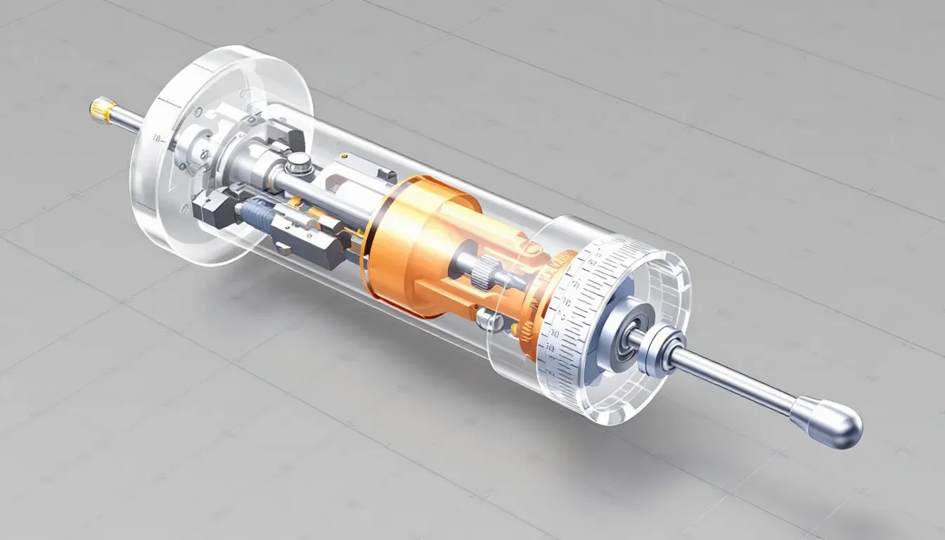
Selecting appropriate equipment is essential for precise measurement of cylindricity. The chosen tools should be capable of examining the entire surface area to provide a thorough analysis of the cylindrical form. Ensuring accurate measurements is key to preserving the component’s structural integrity, adherence to design criteria, and its ability to function as intended.
Different techniques exist for measuring cylindricity, each offering benefits and constraints. Subsequent sections will delve into how instruments designed for assessing roundness and coordinate measuring machines (CMMs) can be utilized to secure exact measurements in evaluating cylindricity.
Using Roundness Measuring Instruments
Various methods can be employed for the measurement of cylindricity, including contact techniques that utilize tools such as micrometers and dial indicators, as well as non-contact approaches like those involving laser scanners. A roundness measuring instrument excels in identifying both radial and longitudinal deformations on cylindrical components, delivering precise evaluations of their shape.
To accurately evaluate the form of cylindrical items, these instruments often incorporate a rotating table which spins the piece being examined while measurements are taken using a stylus. By fixing the object to a revolving platform and employing a sensor to collect data on its surface at numerous points ensures comprehensive examination. This process results in accurate determinations of an object’s roundness.
Using Coordinate Measuring Machines (CMM)
Coordinate measuring machines (CMMs) provide substantial benefits for measuring cylindricity due to their high precision and capability to simultaneously record multiple geometric points. These machines facilitate the capture of numerous points on a surface from diverse perspectives, improving both flexibility and accuracy in documenting the geometry of an object.
By conducting measurements at different angles, CMMs gather an extensive array of data points from across the cylindrical component’s surface. This precise data collection is crucial for verifying that the part conforms to its specified form and tolerance parameters.
Cylindricity vs Circularity
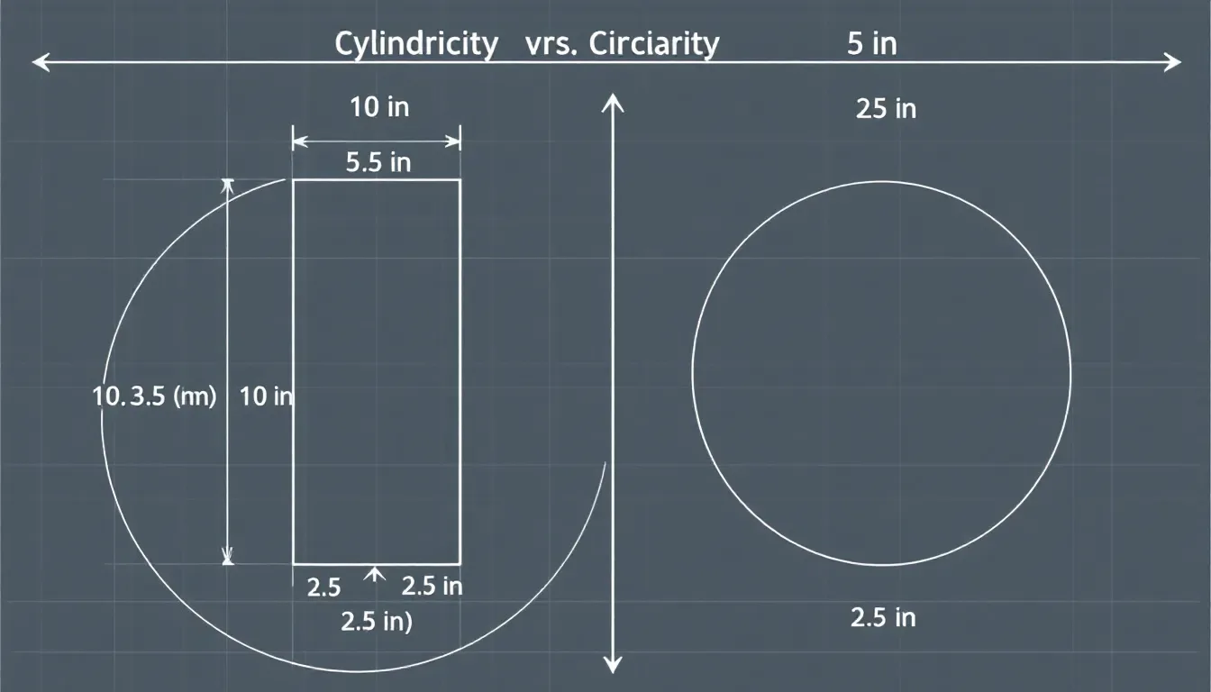
Cylindricity is a measure that incorporates elements of both circularity and straightness to determine if the entire cylindrical form aligns with an ideal cylinder. Circularity evaluates just one cross section’s roundness, but cylindricality guarantees uniform consistency across the whole length of the cylindrical feature.
While circularity focuses on assessing if each individual cross-section within the cylinder achieves perfect roundness, cylindricality examines whether this roundness persists throughout the full extent of the cylindrical part. Thus, it confirms consistent shape retention over its total length.
To differentiate between them: imagine cylindricity as checking whether a column made from stacked coins does not waver from top to bottom, whereas circularity ensures that each coin is perfectly round when looked at separately. Such an example demonstrates how cylindricality combines both aspects – ensuring each slice’s circular precision along with maintaining straight surfaces – for comprehensive control over overall cylindrical geometry.
Cylindricity vs Total Runout
Total runout constitutes a composite inspection which encompasses both the axial and radial disparities, while cylindricality entails an examination of three-dimensional deviations spread over the entire surface of a cylindrical element. Total runout scrutinizes for any anomalies on the surface by employing a particular axis as its reference point, in contrast to cylindricality, which appraises the complete shape of the cylindrical feature independently from such specific references.
In conducting measurements for total runout, it’s imperative that variations across the surface remain within defined boundaries – with emphasis placed on overall variation rather than pinpointing precise geometric fidelity. Conversely, cylindricality provides leeway within its designated tolerance zone—granting a more lenient yet thorough method in confirming that a cylindrical part retains its intended form.
Applications of Cylindricity
Cylindricity is a crucial parameter for components like shafts and pins that must maintain roundness and straightness along their axis. Ensuring this geometric precision is essential to guarantee proper fit within assemblies, thereby avoiding undue wear or functionality problems during operation.
In the realm of automotive engineering drawings, one can frequently encounter the cylindricity symbol, which underscores its significance in mechanical systems design. To measure cylindricity with high accuracy, Coordinate Measuring Machines (CMMs) are often employed. They provide versatility in evaluating intricate geometries typical of automotive parts, confirming adherence to rigorous design specifications.
Challenges in Measuring Cylindricity
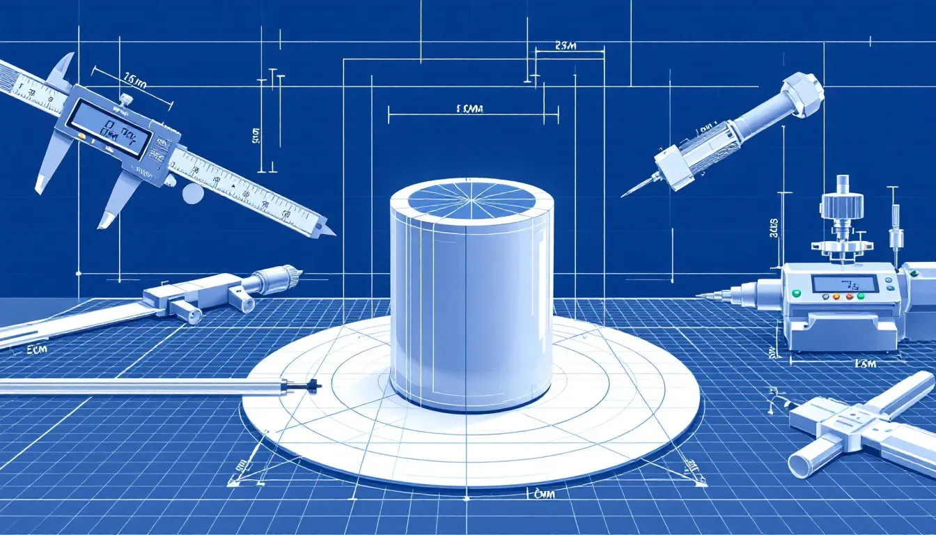
Gauging the cylindricality of a cylindrical part presents considerable challenges, such as its time-intensive nature and complexity. To these difficulties, there is also a need for sophisticated technology and the utilization of Coordinate Measuring Machines (CMMs). These hurdles can be particularly burdensome for smaller manufacturing operations that require stringent precision levels for specific uses.
When taking measurements with instruments designed to assess roundness in order to accurately determine cylindricity, it’s imperative to correctly position the sample. It’s vital that the axis of the cylindrical component being measured is perfectly aligned with that of the measuring apparatus so as to guarantee measurement results are both reliable and accurate.
Importance of Accurate Cylindricity Measurements
It’s essential to achieve precise cylindricity measurements in order to prevent issues during high-speed operations, as imbalances can impair the functionality due to wobbling. For components such as sliding shafts, it is imperative that they retain a uniform cylindrical shape and straightness for them to fit appropriately and function effectively within assemblies with narrow tolerances.
By carrying out meticulous cylindricity checks, surface flaws like depressions or protuberances are detected that could remain unnoticed without proper measurement precision. Such quality control measures enhance the efficiency and durability of mechanical systems by guaranteeing an exact interlocking of parts and their seamless operation.
If there’s a lack of precision in measuring cylindricity, this may lead to increased abrasion among moving parts, which often results in early breakdowns. Precise fitting of components achieved through accurate measurements mitigates production expenses while improving the performance of assembled machinery.
Tips for Applying Cylindricity in Design
Manufacturers can benefit from employing cylindricity to expand the tolerance of diameters, thereby simplifying the machining process while still maintaining the essential functionality of parts. It’s vital for designers working on cylindrical components to include considerations for both straightness and roundness within their tolerating strategies to ensure correct operation.
When deciding whether to apply circularity or cylindricity in design, it is important that designers take into account the precision needed by the specific application. They should contemplate performing a statistical tolerance stack-up analysis to gauge how implementing cylindricity affects fit and function within an assembled product. For situations where taper isn’t a crucial factor, opting for circularity may streamline measurements and cut down on production expenses.
Summary
To sum up, the concept of cylindricality in Geometric Dimensioning and Tolerancing (GD&T) is a vital element for guaranteeing that cylindrical components adhere to their intended shape and functionality within established limits. Recognizing how cylindricity differs from circularity and total runout is crucial for both designers and those involved in manufacturing. The use of precise measurement methods, which could include roundness measuring devices or coordinate measuring machines (CMMs), is fundamental to obtaining the required level of accuracy.
Incorporating considerations of cylindricity into design processes enables more lenient tolerances while enhancing efficiency during production, thereby contributing to mechanical systems with superior performance characteristics. Mastery over the methodologies used for assessing cylindricality can improve various qualities such as dependability, operability, and durability across an array of applications involving cylindrical parts.
Frequently Asked Questions
What is the difference between cylindricity and circularity?
Cylindricity evaluates the overall shape of a cylindrical object along its length, whereas circularity focuses solely on the roundness of its cross-sectional areas.
How is cylindricity measured?
Cylindricity is measured using roundness measuring instruments or coordinate measuring machines (CMMs), which provide a thorough assessment of the cylindrical shape.
These tools are essential for ensuring precision in measurement.
What are the common applications of cylindricity?
Ensuring the precision of components like shafts and pins within automotive parts and diverse mechanical assemblies is critical, for which cylindricity plays a vital role.
By applying this principle, reliable operation is achieved as it preserves uniform roundness as well as linearity throughout an axis.
What challenges are faced in measuring cylindricity?
The process of measuring cylindricity involves intricate and time-consuming steps, necessitates the use of sophisticated equipment such as coordinate measuring machines (CMMs), and demands that the part being measured is correctly aligned.
It’s crucial to overcome these obstacles in order to achieve precise measurement outcomes.
Why is accurate cylindricity measurement important?
Accurate cylindricity measurement is vital as it ensures proper part fit, minimizes wear, and enhances performance in mechanical systems.
This directly contributes to the reliability and longevity of high-speed applications.
Simplify Procurement – Start Your Next Project with LKprototype
LKprototype simplifies procurement for custom manufacturing, from 3D Printing to CNC Machined Parts and Vacuum Casting to prototype your product or parts, with a focus on speed and efficiency. Our platform provides instant quotes. With LKprototype, You can connect with the team to communicate your project to ensure quality and on-time delivery.
Start with an instant quote and experience how our technology and expertise can make custom part procurement faster and easier.
 LKprototype

