 LKprototype
 G-code is the primary language CNC machines use to execute precise tasks, commonly referred to as g code in CNC. This article explains what G-code is, how it functions in CNC machining, and the essential commands you need to know.
Key Takeaways
G-code is a crucial programming language for CNC machines, automating tasks that enhance precision and repeatability in manufacturing.
Understanding key G-code commands, such as G00 for rapid movement and G01 for linear interpolation, is essential for optimizing machining processes.
Differentiating between modal and non-modal G-codes, as well as utilizing advanced techniques like canned cycles, significantly improves CNC programming efficiency and machining accuracy.
What is G Code in CNC?
G-code, also referred to as “geometric code,” is the fundamental element of CNC programming. This specialized coding language directs CNC machines on how to execute various actions like moving to designated coordinates, cutting materials, and carrying out intricate machining tasks. G-code acts as a conduit between the digital designs produced in CAD software and the tangible operations performed by machine tools, which includes creating a g code file.
In the realm of CNC machining, G-code’s main role is to mechanize functions that would typically need manual control. This automation ensures precision and uniformity within manufacturing workflows. By deciphering g code commands, CNC machines can carry out assignments with remarkable accuracy—making them vital for industries where stringent tolerances and consistent quality are paramount, such as aerospace engineering, automotive production, or medical equipment manufacturing.
For those engaged in cnc programming activities must comprehend g codes due to their integral role in ensuring efficiency throughout the entire machinery process.
Reading and Interpreting G Code Commands
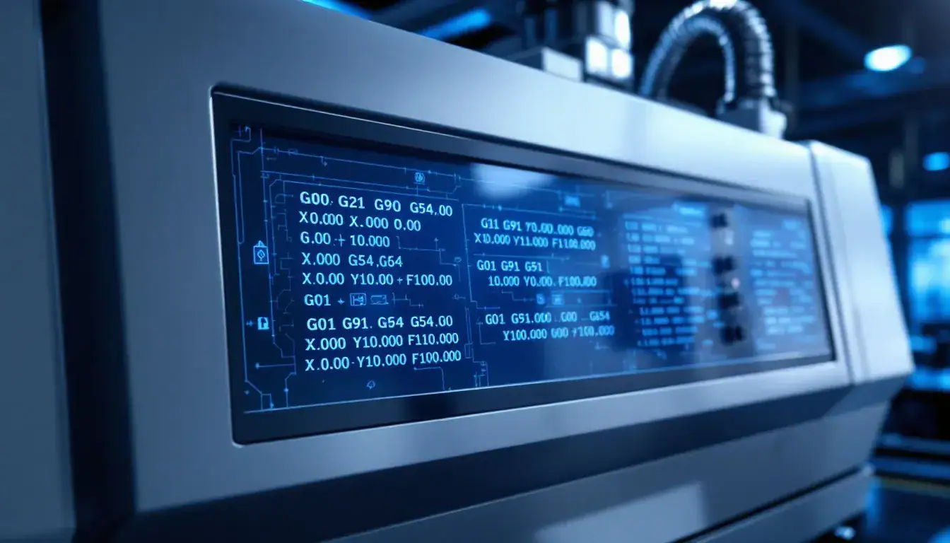
Mastering the interpretation of G-code is crucial for effectively controlling CNC machines. This expertise is vital for engineers, operators, and users to comprehend what actions the machine will undertake. Typically, CAM software translates CAD models into G-code to refine the machining process. A conventional G-code program kicks off with a ‘%’ character and adheres to a distinct sequence ranging from O0001 to O9999.
Commands such as G01 enable the machine tool’s movement in a straight line at a determined feed rate. Employing absolute mode, an instruction like G01 X10 Y5 positions the tool at specific coordinates originating from an established zero point. In contrast, while operating in relative mode, this same command would relocate the tool based on its present location by shifting it toward new coordinates. Grasping these subtle differences is indispensable for achieving precision during machining operations and precluding mistakes.
Additional common g code commands encompass things like G20, which determines units as inches, and also includes instructions such as those found under syntax starting with G90, facilitating absolute positioning. These are just elements within an extensive list of g codes that machinists should become well-acquainted with so they can carry out efficient programming tasks seamlessly when managing their CNC machinery processes.
Key G Code Commands for CNC Machining
Essential G-code commands lie at the heart of CNC programming, ensuring meticulous control over a CNC machine’s movements and functionality. Critical instructions include G00 for swift positioning, G01 to achieve linear interpolation, and the combination of G02/G03 for executing circular interpolation. These are vital in crafting precise toolpaths that lead to both efficient machining processes and superior quality outputs.
Commands like G28 play an important role by returning the tool to its home position on the CNC machine. Similarly, selecting the appropriate working plane with commands such as G17 (XY plane), G18 (XZ plane), and G19 (YZ plane) is paramount for directing movement accurately. Collectively these codes comprise an extensive list that machinists must thoroughly understand in order to facilitate smooth operation within their CNC endeavors.
G00 – Rapid Movement
The G00 command plays an essential role in the swift relocation of tools within a CNC machine, enabling rapid traversing to designated coordinates without engaging in the cutting operation, thereby considerably reducing machining time. By commanding all axes to move concurrently along a straight line, it assures expedited travel between various process points.
Despite its benefits for speed enhancement, caution is necessary when employing rapid movements due to possible impediments like clamps, vices or workpieces that could intersect with the tool’s trajectory and cause accidents. When used judiciously, the G00 command can significantly trim down on machining duration while simultaneously preserving both accuracy and safety standards.
G01 – Linear Interpolation
The G01 command plays a pivotal role in linear interpolation, directing the CNC machine to execute movements along a straight line at a predetermined feed rate. This instruction is essential for precision in tasks like linear cutting and material extrusion, which are vital for detailed and precise machining outcomes.
When utilizing the G01 command, machinists define the desired end position by providing specific X, Y, and Z coordinates that govern the tool’s trajectory. Proficiency with the G01 command is key to enabling operators to reliably craft parts of high quality and accuracy through their CNC programming.
G02 and G03 – Circular Interpolation
The commands G02 and G03 play a vital role in circular interpolation, with the former directing the machine tool’s movement in a clockwise direction while the latter guides it counterclockwise. These instructions are indispensable for generating paths that allow tools to carve out elaborate patterns and intricate geometries.
When using the G02 command, one must define both endpoint coordinates as well as define the pivot point of rotation. This is commonly achieved through employing I and J parameters which establish an offset from where motion originates to its central axis. Similarly, executing a seamless and unbroken circular path using G03 necessitates inputting these same details.
Integrating linear moves by applying G01 alongside circulatory motions brought about by combining both G02 and G03 facilitates fashioning complex yet accurate pathways for machining purposes.
Modal vs Non-Modal G Codes
Grasping the difference between modal and non-modal G-codes is essential for proficient CNC programming. Modal G-codes, once set, stay active until a new command supersedes them. This feature streamlines programming by eliminating the need to restate commands frequently. For instance, G90 (absolute positioning) and G91 (incremental positioning) are examples of modal codes that remain operational until they’re altered.
In contrast, non-modal commands have a one-time effect. They do not maintain their influence beyond their initial execution. Non-modal instructions such as G28 – which instructs the machine to revert to its home position – and changing measurement units with either code: ‘G20’ or ‘G21’ illustrate this category.
Recognizing whether a given piece of coding is considered modal or non-modal is vital for accurate control over CNC machines in order to optimize efficiency during use.
Common M Code Commands
M-codes play a crucial role in CNC machining by governing non-geometric functions that are essential to the operation, such as controlling spindle rotation, managing coolant flow, and executing tool changes. An example of this is M00 which halts all machine activity for operator intervention, while M05 ceases spindle movement which is necessary when changing tools or completing a job.
Additional examples of commonly used M-codes include M08 that activates the coolant system and M30 that marks the completion of a program while resetting the machine for subsequent operations. Mastery over these codes is key to automating numerous functions and guaranteeing efficient CNC machine performance.
CAD and CAM Software in G Code Programming
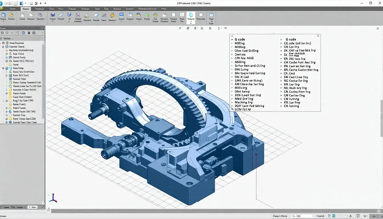
In the realm of CNC machining, the fusion of CAD and CAM software plays a critical role in creating an efficient transition from digital design to actual part fabrication. The use of CAD software enables designers to craft detailed part designs, encompassing all necessary dimensions and characteristics. These details are subsequently translated into G-code by means of CAM software, which is a pivotal step for enabling CNC machines to interpret and follow the intended toolpaths.
Selecting appropriate CAD and CAM solutions is imperative for maximizing efficiency within CNC machining operations. It’s important to conduct checks on the G-code through simulations before commencing with physical manufacturing in order to detect any potential issues that could result in expensive errors. By adeptly integrating these systems and practices, one can augment productivity while minimizing the need for manual intervention during code programming stages – ultimately leading to more precise and reliable G-code programming outcomes.
Tool Length Compensation and Work Offsets
Maintaining accuracy during CNC machining is essential, and this is where tool length compensation and work offsets become crucial. Tool length compensation allows for adjustments to be made in response to differences in the lengths of tools, making certain that the cutting device interacts with the material as intended. In contrast, work offsets establish a precise starting point on the actual piece being worked on relative to the coordinate system of the machine itself, ensuring cuts are made correctly based on how it’s set up.
The implementation of both these methodologies plays an integral role in minimizing errors and improving the efficiency within which CNC machines operate. Mastery over incorporating both tool length compensation and work offsets into their practice stands as critical competencies for machinists aiming at excellence in their craft.
Tool Length Compensation
Compensating for variations in tool length is a vital element of CNC machining, as it ensures the accurate placement of tools by accounting for their differing lengths. This process helps to sustain the appropriate cutting depth essential for precise operations. Tool length compensation not only aids in avoiding potential collisions and excessive cutting, but also contributes to extending the lifespan of tools by preventing expensive mistakes.
In order to adjust for these discrepancies throughout the machining process, the G43 command plays an integral role, guaranteeing precise and uniform outcomes.
Work Offsets
Work offsets play a pivotal role in pinpointing the precise zero position of a workpiece, which is critical for ensuring precision during the machining process. These offsets maintain consistency by aiding tools in consistently aligning with the proper reference point.
When established accurately, work offsets permit CNC machines to flawlessly carry out their programmed instructions, anchoring each new piece from an accurate starting location. This strategy is vital for precisely positioning the tool in relation to the workpiece and is essential for realizing intended results.
Safety Considerations When Programming G Code
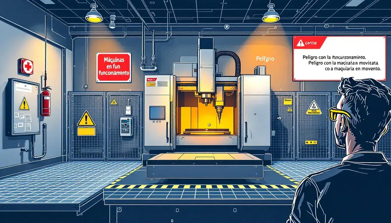
When programming G-code, the utmost importance should be placed on safety. To avert possible collisions during swift motions, programmers must maintain a clearance of no less than 1mm. Employing appropriate toolpath strategies is essential in decreasing collision risks and preventing tools from breaking while in use.
It’s vital to fasten workpieces firmly to diminish dangers associated with shifting during the machining process. Maintaining safety standards in G-code programming is imperative for avoiding mistakes, protecting tools from damage, and steering clear of perilous conditions.
Simple G Code Program Example
A basic example of a G-code program can serve as an introduction to the essential commands and formats involved in CNC programming. For instance, using a G-code command such as G01 X247.951560 Y11.817060 Z-1.000000 F400.000000 directs a linear move to a designated location at an established feed rate, which is vital for mastering g code programs and boosting your skills in CNC machinery operations.
To illustrate Consider that within the realm of simple g code programs one could include instructions designed to fabricate a circle with a 1-inch radius situated at the center point (origin). Grasping these elementary commands is pivotal when it comes to devising accurate and efficient CNC programming schemes.
Advanced G Code Techniques
Enhancing CNC machining’s effectiveness and accuracy can be achieved through sophisticated G-code methods. By integrating G01 with curves generated by G02 and G03, the creation of intricate toolpaths for diverse forms is made possible. The programming process is greatly streamlined by using canned cycles, which diminishes the quantity of code needed to carry out repetitive actions.
For those who aim to attain complex designs while optimizing efficiency in CNC machining, these advanced techniques are crucial. Acquiring proficiency in them unlocks fresh opportunities within the realm of automated manufacturing.
Canned Cycles
Canned cycles are designed to simplify the machining process for repetitive tasks such as drilling and tapping, by condensing a series of G-codes into one single command.
These canned cycles cover:
Standard drilling with G81
Counter-sinking with G82
Tapping operations using G84
High-speed peck drilling through code G73, which is specifically tailored for efficient chip breaking while drill holes.
By employing these canned cycles, the efficiency of the programming process is significantly improved due to their simplifying effect.
Cutter Compensation
Cutter compensation enhances the accuracy of the machining process by adjusting for both the radius and length of the tool. It does this by altering the tool path to guarantee that cutting takes place exactly where it should in relation to the programmed trajectory.
Employing cutter compensation is essential not only for meeting precise specifications but also for upholding a high standard of precision within machining operations, especially when considering factors like spindle speed.
Applications and Benefits of G Code in CNC Machining
G-code plays a vital role in precision CNC machining within sectors like aerospace, automotive, and medical devices due to its ability to achieve high accuracy necessary for tasks demanding strict tolerances.
The use of G-code significantly accelerates the production process by facilitating quick prototyping and manufacturing on a smaller scale. The implementation of sophisticated G-code methodologies boosts both the efficiency and exactness of CNC processes, allowing for the automation of intricate machining activities.
Summary
In this comprehensive guide, we’ve explored the complex world of G-code, essential for anyone looking to gain proficiency in CNC machining. Grasping everything from basic commands to sophisticated programming skills is imperative. With a solid understanding of primary codes like rapid movement (G00), linear interpolation (G01), and circular interpolation through the use of G02/G03 commands, you can drastically improve your ability to command CNC machines.
Understanding the crucial roles that tool length compensation and work offsets play in preserving precision is just as important as learning these code commands. Incorporating safety measures and effectively employing CAD and CAM software are key factors for executing flawless CNC operations. Equipped with an extensive knowledge base on G-code usage, you’re now prepared to unlock its full potential within your automated manufacturing projects. Let these insights empower you toward reaching unparalleled levels of achievement in automated production systems.
Frequently Asked Questions
What is G-code in CNC milling program?
G-code is a programming language utilized in CNC milling that directs the movements of the cutting tool. It consists of specific instructions that the CNC machine’s microcontroller interprets to execute precise operations.
What is the most common G-code?
The most common G-codes are G00 for rapid movement, G01 for linear movement, G02 for clockwise circular movement, and G03 for counterclockwise circular movement.
Understanding these codes is essential for effective CNC programming.
How does tool length compensation improve machining accuracy?
Tool length compensation significantly improves machining accuracy by accounting for variations in tool length, ensuring proper cutter engagement with the material and maintaining the correct depth of cut.
This results in reduced errors and enhanced tool life.
What are some common M-code commands in CNC machining?
Common M-code commands in CNC machining include M00 for stopping the machine, M05 for stopping the spindle, M08 for activating coolant, and M30 for concluding a program and resetting the machine.
Understanding these commands is essential for effective CNC operation.
How do CAD and CAM software contribute to G-code programming?
G-code programming is significantly facilitated by the integration of CAD and CAM software, which converts digital designs of parts directly into G-code. This advancement simplifies the manufacturing process flow and reduces errors before actual machining takes place.
The synergy between these software systems bolsters both effectiveness and precision during the production cycle.
Still, need help? Contact Us: lk@lkprototype.com
Need a PROTOTYPE or PARTS machining quote? Quote now